CAB
™
16 Series User Manual
Page 18 http://aa.peavey.com copyright 2000 All Rights Reserved
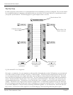
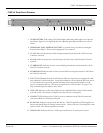
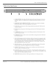
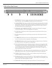
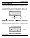
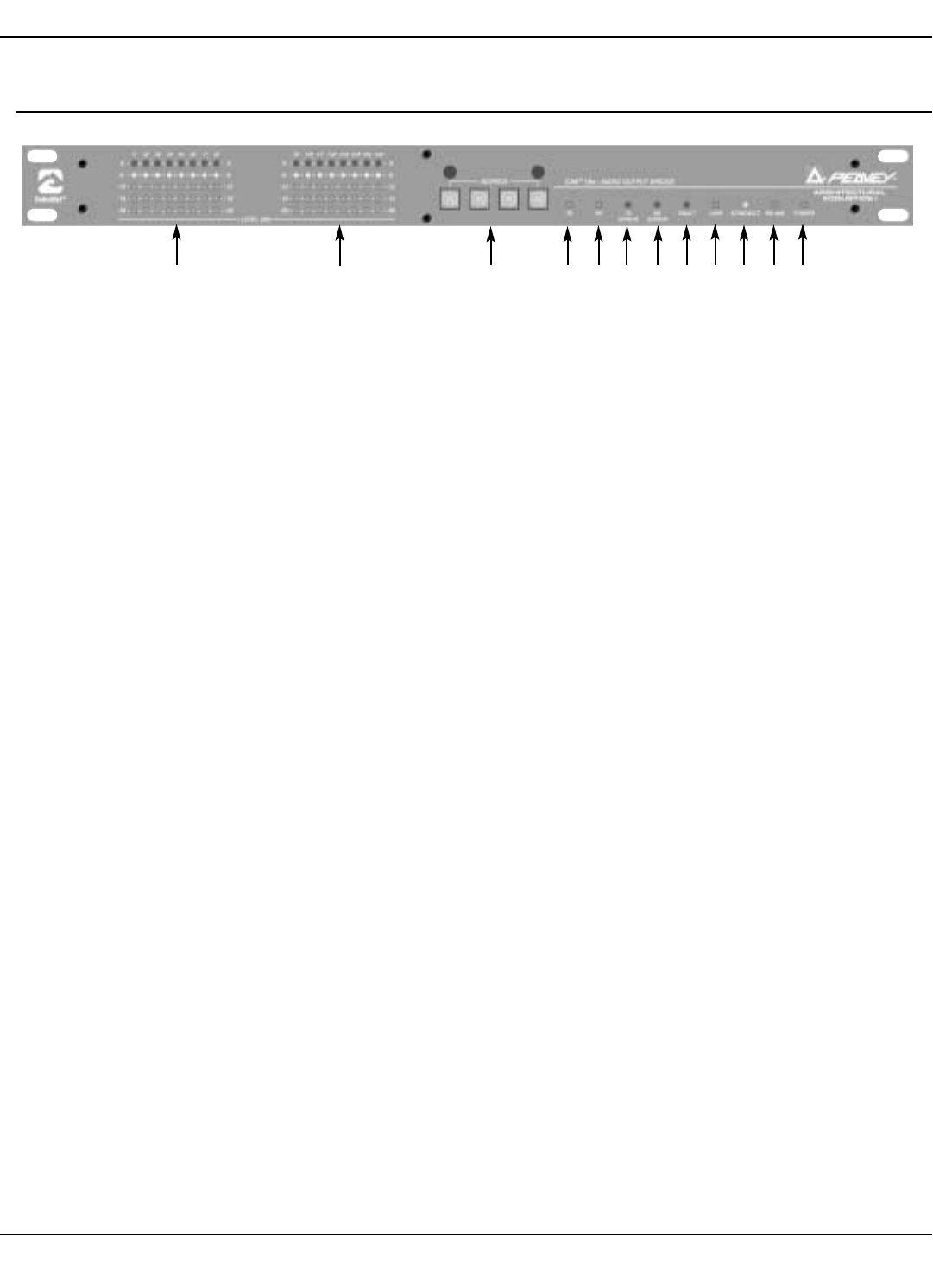
CAB 16o Front Panel Features
1 2 3 4 5 6 7 8 9 10 11
1
AUDIO METERS Peak reading LED ladder displays indicating audio input level in the ana-
log domain. Signal level is displayed after the adjustable gain stage and before the A/D con-
verters.
HARDWARE BASE ADDRESS SWITCHES 4-position rotary switches for setting the
hardware base address. Shown with tamperproof cover removed.
TX LED Indicates the presence of data being transmitted (sent) from the CAB 16 onto the
CobraNet
™
network.
RX LED Indicates the presence of data being received into the CAB 16 from the CobraNet
network.
TX ERROR LED Indicates an error occurred during transmission of data from the CAB 16
onto the CobraNet network.
RX ERROR LED Indicates that an error occurred while receiving data into the CAB 16 from
the CobraNet network.
FAULT LED Illumination of the Fault indicator indicates detection of an unexpected condi-
tion within the CobraNet interface. Some fault conditions will also light the RX Error and/or
TX Error indicators to give more specific indication if the unexpected condition is in the
receive or transmit processes. The errors are reported by a series of flashes. See page 37 for
help on identifying error codes for the CAB 16.
LINK LED Indicates a valid control link has been established between the CAB 16 and the
network switch. This function is duplicated in the software control panel.
CONDUCT LED Indicates the CAB 16 is an active conductor on the CobraNet network.
Only one conductor is allowed per network.
RS-485 LED Indicates activity on the RS-485 bus. This LED should be OFF during idle con-
ditions and should blink ON during normal activity. (If this LED stays ON during idle, it may
indicate an RS-485 conductor polarity inversion.)
POWER LED Indicates that the CAB 16 is powered from an AC mains power source.
1.
2.
3.
4.
5.
6.
7.
8.
9.
10.
11.


