


7
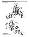
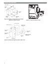
E. TANKLESS HEATER OR COVERPLATE
1. If a tankless coil is used (item 9), install as pictured.
On water boilers, install in opening in front section.
On steam boilers, install in opening in rear section.
For suggested piping of tankless water heaters refer
to Figures 3.3 and 3.4.
2. If not using a tankless coil, cover the heater opening
with cover plate (item 7 or 16).
F. CONTROLS
1. Water Boiler Controls:
a. Install the limit / operating control, pressure-
temperature gauge and safety relief valve.
See Figure 7.1 (Section 7) for proper location.
For installations subject to UL726, a second
operating control that senses water temperature
is also required (not provided). Use an L4080B
or equivalent. Install in the supply piping near
the boiler.
2. Steam Boiler Controls:
a. Install the limit / operating control, pressure
gauge, gauge glass trim and safety relief valve.
See Figure 7.2 (Section 7), Figure 3.7 (float
boilers) and cover photo (probe boilers).
b. For installations subject to UL726, a second
operating control that senses steam pressure is
required (not provided). Use a PA404A or
equivalent. On probe boilers, install the
additional pressure control opposite the
standard PA404A using a cross instead of a
tee along with a second brass siphon (not
provided). On float boilers, install the additional
pressure control in the 1/4" tapping on the top of
the float low water cut-off using a vertical (360º)
brass siphon (not provided).
c. For application of a probe low-water cut-off,
use only Hydrolevel CG450. See Figure 7.2
(Section 7) for location. See also control
manufacturers instruction sheet.
d. See Figure 3.7 for application of float low water
cut-offs.
3. For complete information on servicing and
adjustment of controls, refer to the attached control
specification sheets.
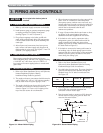
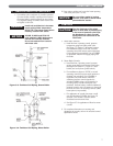
PIPING AND CONTROLS
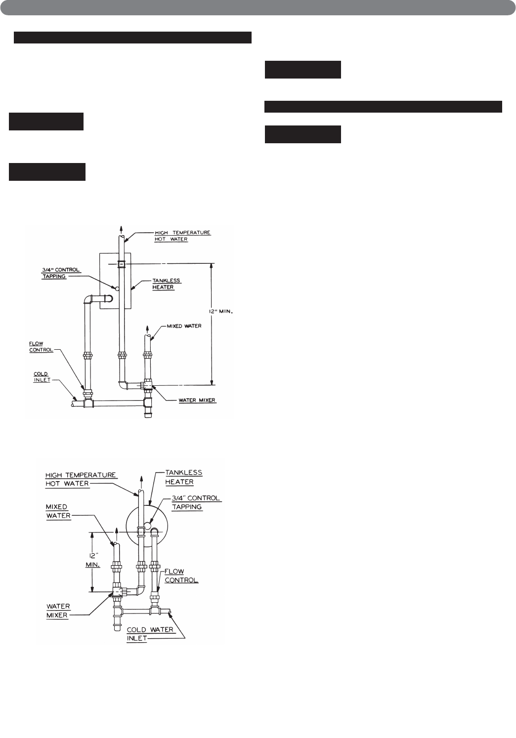
Figure 3.3: Tankless Coil Piping, Steam Boiler
Figure 3.4: Tankless Coil Piping, Water Boiler
Pipe the discharge of the safety
valve or relief valve to prevent injury
in the event of pressure relief. Pipe
the discharge to a drain. Provide
piping that is the same size as the
relief valve.
CAUTION
Be sure rubber gasket is in place
between cover plate or water heater
plate and boiler section.
NOTICE
X1019R, X1020R, and PP1011R
coils installed in WBV boilers have
internal flow controls installed.
Do not use external flow controls
with these coils.
NOTICE
Install anti-scald device in hot water
supply piping. Water temperature
above 125°F can cause severe burns
instantly or death from scalds.
DANGER