


A. PRESSURE TEST BLOCK ASSEMBLY
1. Make up cold water supply connection to the boiler.
2. Install pressure gauge or pressure-temperature gauge
in tapping provided. See Boiler Dimensional
drawing, Figures 7.1 and 7.2 (Section 7)
3. Plug all open tappings in the boiler and fill with
water. Apply approximately thirty (30) psig pressure.
Check to make certain that all joints and fittings are
water tight.
4. After all joints and connections have been proven
tight, remove cold water supply and plugs from all
tappings that are to be used. See Figures 7.1 and 7.2
(Section 7) for tapping locations.
B. BOILER RETURN CLEARANCE
Return piping must allow for opening and closing
Burner Mounting Plate. PB Heat, LLC suggests installing
a 1-1/4 NPT tee, a 90° elbow, and a 1-1/4 NPT x 5"
long nipple in the return tapping before a vertical stand
pipe is used.
C. WATER BOILER PIPING
1. Refer to the Water Installation Survey and Hydronics
Institute Residential Hydronic Heating
Installation/Design Guide for guidance.
2. The supply and return connections should be sized to
suit the system. A 1-1/2" to 1-1/4" reducing coupling
may be used where the system piping is 1-1/2".
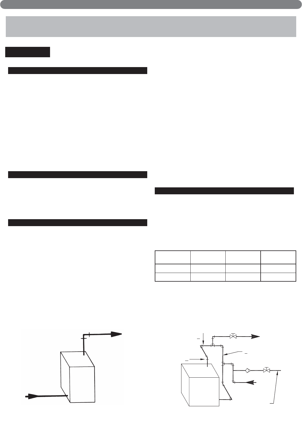
3. The supply should be out the top of the back section
and return to the bottom of the front section as
shown in Figure 3.1. There is a 3/4" tapping in the
top of the back section for air elimination.
4. When the return temperature from the system will be
below 150°F on oil boilers for extended periods
(heat pump systems, outdoor reset, snow melt, etc.),
provide piping and controls to protect the boiler from
condensation. Condensation will damage the boiler
and will lead to shortened boiler life and
maintenance problems.
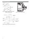
5. If using a Partner indirect fired water heater or other,
see Figure 3.6 for typical piping. Also refer to
additional instructions supplied with the Partner.
6. If the boiler is to be used in conjunction with a
refrigeration system, the chilled medium shall be
piped in parallel with boiler and proper valves
applied to prevent the chilled medium from entering
the boiler. Refer to Figure 3.5.
7. If the boiler is connected to heating coils located in
air handling units, the boiler piping system must be
equipped with flow control valves or other automatic
devices to prevent gravity circulation of the boiler
water during the cooling cycle.
D. STEAM BOILER PIPING
1. Refer to the Steam Installation Survey and
Hydronics Institute Residential Hydronic Heating
Installation/Design Guide for assistance.
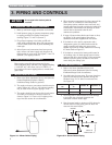
2. See table below for pipe sizing. The return loop from
system should always enter equalizer through the
Hartford Loop, 2" to 4" below normal water line.
See Figure 3.2.
3. Use swing joints to attach header to avoid damage
to the boiler due to thermal expansion and
contraction of steam header pipe.
4. Pipe the steam header a minimum of 24" above the
normal water line using swing joints to attach the
risers into the steam header.
3. PIPING AND CONTROLS
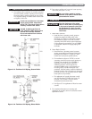
Figure 3.1: Water Boiler Piping
Figure 3.2: Steam Boiler Piping
PIPING AND CONTROLS
MAKE–UP
CONNECTION
HEADER
RISER
EQUALIZER
B
A
C
Boiler Model
No.
Supply Riser
"A"
Header "B" Equalizer "C"
WBV-03 (1) 2" 2” or 3” 1-1/4"
WBV-04 (1) 2" 2” or 3” 1-1/4"
6
Do not pipe boiler before jacket is
installed.
NOTICE