7
D. WATER BOILER PIPING
1. Refer to the Water Installation Survey and Hydronics
Institute Residential Hydronic Heating
Installation/Design Guide for Guidance.
2. The supply and return connections should be sized
to suit the system.
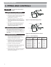
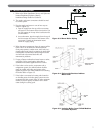
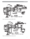
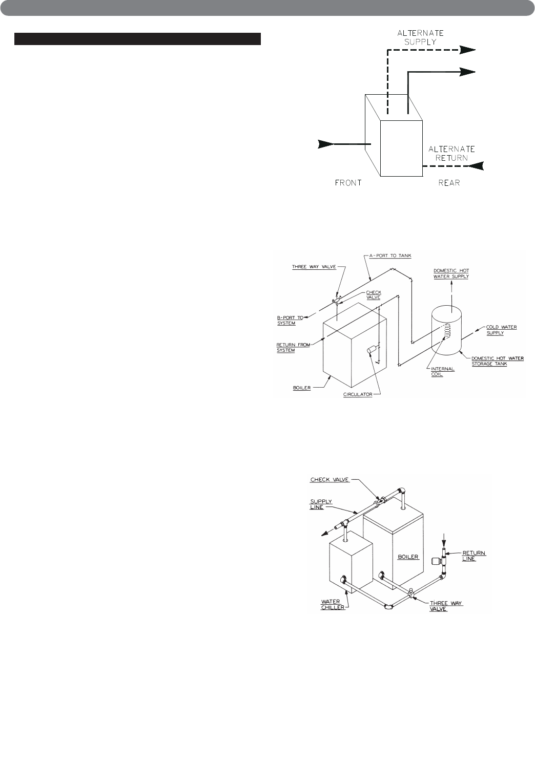
3. Pipe the supply and return in one of two ways as
shown in Figure 3.3:
a. Pipe the supply from the top of the rear section
and return to the bottom of the front section. Use
the 3/4" tapping in the top of the back section for
air elimination.
b. As an alternative, pipe the supply from the top of
the front section and return to the bottom of the
rear section. Provide air elimination means
within the supply piping.
4. When the return temperature from the system will be
below 150°F on oil boilers for extended periods
(heat pump systems, outdoor reset, snow melt, etc.),
provide piping and controls to protect the boiler from
condensation. Condensation will damage the boiler
and will lead to shortened boiler life and
maintenance problems.
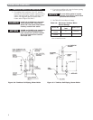
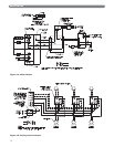
5. If using a Partner indirect fired water heater or other,
see Figure 3.4 for typical piping. Also refer to
additional instructions supplied with the Partner.
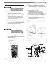
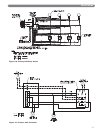
6. If the boiler is to be used in conjunction with a
refrigeration system, the chilled medium shall be
piped in parallel with boiler and proper valves
applied to prevent the chilled medium from entering
the boiler. Refer to Figure 3.5.
7. If the boiler is connected to heating coils located in
air handling units, the boiler piping system must be
equipped with flow control valves or other automatic
devices to prevent gravity circulation of the boiler
water during the cooling cycle.
PIPING AND CONTROLS
Figure 3.3: Water Boiler Piping
Figure 3.4: Piping with Peerless Indirect
Water Tank
Figure 3.5: Isolating Boiler from Chilled Medium
on Chiller Systems


