


14
BURNER SETUP & BOILER OPERATION
A. BURNER INSTALLATION
1. The oil burner is supplied with a mounting flange
fixed in position.
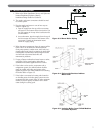
2. Mount the burner to the Burner Mounting Plate
(item 3) with four (4) 5/16" studs and nuts provided.
3. Care must be taken when routing the oil lines so not
to interfere with the opening and closing of the
burner mounting plate. Flexible oil lines or flared
copper disconnects with valves (when copper lines
are used) may be installed to assure full opening of
the burner mounting plate when servicing.
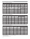
4. Oil burner specifications:
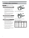
For information pertinent to the oil burner such as
nozzle sizing, fuel supply piping, adjusting or
servicing, refer to the charts in this section and the
burner installation manual.
B. BURNER START-UP AND ADJUSTMENT
1. Burner should start automatically when thermostat is
turned up and main boiler service switch is turned
on. If burner does not start, check to be sure there is
oil in the tank and push reset button on burner
control:
Beckett: Square red button.
Carlin: Round red button.
Riello: Round red button inside clear flexible
cover on back of burner cover.
If burner still does not start, contact serviceman.
2. Adjust burner and barometric draft control for
highest CO
²
(Maximum 13% [EC-03 - EC-05] or
12-1/2% [EC-06]) while maintaining a 0 Smoke and
-.01 to -.02" W.C. draft overfire.
All adjustments must be made using suitable
instruments such as found in a Bacharach
Combustion Test Kit.
3. Burner and boiler can be shut down by turning
down the thermostat and moving the main boiler
service switch to the "off" position.
4. See burner manufacturer's manual for further
information regarding the burner.
C. CHECK BOILER CONTROLS
1. Limit and Operating Controls:
a. Lower the set point of each control until the
burner shuts down. Note that the system pressure
(or temperature) corresponds to the desired set
point.
b. Return the controls to the desired set point.
2. Low Water Cut-off (if used) - consult the
manufacturer's instructions for the low water cut-off
operational check procedure.
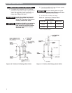
D. PURGE AIR FROM THE SYSTEM
(WATER BOILERS ONLY)
1. Purge the system using purge valves, isolating zones
in the process or use system vents. Do not operate
the pump(s) while purging. Pumps will hold air in
the eye of the impeller.
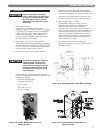
2. Allow the system to reach 180°F and use manual
vents, if installed, to remove any remaining air.
Watch the pressure gauge as the system approaches
180°F. If the pressure exceeds the design operating
pressure, check:
a. Fill valve pressure.
b. Expansion or compression tank operation and
sizing.
5. BURNER SETUP & BOILER OPERATION
Burn only #2 Fuel Oil in this
appliance. Do not use gasoline,
crankcase drainings or any oil
containing gasoline.
CAUTION
Do not attempt to start the burner
when excess oil has accumulated,
when the unit is full of vapor, or
when the combustion chamber is
very hot.
CAUTION
Be sure hi temp gasket is between
the burner mounting flange and the
Burner Mounting Plate.
NOTICE
Two-pipe oil supply for Riello burner
requires a separate kit. Order part
#C7001026 from Riello dealer.
NOTICE
Do not start the burner unless all
cleanout doors are in place.
CAUTION