


MACH® Series
Gas-Fired Boiler Maintenance
Page 32
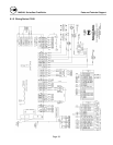
5.4 SEQUENCE OF OPERATION
1. When the On/Off (Main power) switch is turned
on, power is provided through a circuit breaker to
the boiler control and the combustion blower. The
boiler control powers a 24 V transformer. The
boiler control supplies 24 V power through a high
limit temperature switch and a low water level
control.
2. The low water level control is closed when there is
water in the boiler up to the probe.
3. When the temperature sensed by the high limit
temperature control is below the set limit, the
switch is closed. Manual reset of the switch is
required following conditions exceeding high limit
temperature.
4. If either the high limit temperature control or the
low water level control is open, the boiler control
locks out and indicates E 12 on the display.
5. Depending on the settings in the boiler control, a
heat request is generated.
6. The controller checks that the low air pressure
switch is open indicating no airflow. The blower
is driven towards the prestart fan speed. When the
air pressure switch closes the 15 second prepurge
time is started, and the blower is driven toward the
ignition speed.
7. After the 15 second prepurge the gas pressure
switch circuit is checked to ensure the gas pressure
is within design parameters.
8. If there are no lockouts then when the blower
speed is within 200 rpm of the ignition fan speed,
a trial for ignition period of 3 seconds is initiated.
The internal spark generator and the gas safety
shut off / control valves are energized.
9. The internal spark generator is de-energized .3
seconds before the end of the trial for ignition
period. After the trial for ignition period, if a flame
signal is detected by the flame rectification
system, the control initiates a flame stabilization
period of 5 seconds at the ignition rpm of the fan.
The fan is driven to low fire for 1 minute before
the boiler is released to modulation.
10. The unit modulates between the low fire setting
and the high fire setting to maintain the desired
outlet water temp set point.
11. When the load is below the low fire rating of the
boiler the boiler will continue firing and the outlet
water temperature will rise until it reaches the set
point + temperature differential. At this point the
burner is turned off, and the fan continues to run to
post purge the boiler for 15 seconds.
12. When the water temperature is reduced by the load
on the system, a heat request is again generated.
The operating sequence will recycle to step 6,
provided the limits on water level, gas pressure
and high temperature are all met.
5.5
TROUBLESHOOTING
The MACH Series boiler will display service codes to
indicate some problems with the boiler. There are two
types of lockouts the control may experience: manual
reset lockouts requiring an operator to press the reset
button, and automatic reset lockouts, where the control
will automatically attempt to restart the boiler. A
listing of service codes is included at the end of this
section.
Should the unit fail to operate, call a qualified service
technician to troubleshoot the problem and implement
corrective action.
The Loss of Power
In the event of a power failure (or when the On/Off
switch is in the Off position), the display panel is not
illuminated and the entire system is de-energized,
closing all automatic valves and halting all boiler
operations. When power is restored the sequence of
operation will resume at Step 5, provided that all the
limits are satisfied. If any manual reset lockout was
present when the power is lost, the display will flash E
04 when the power is resumed. This indicates that the
control was in lockout mode but does not indicate
which service code was present.