


MACH® Series
Gas-Fired Boiler Installation
Page 27
MACH C750, C900 & C450
Required Tools:
TORX® T40 or 5 mm hex wrench
3 mm or 7/64 in hex wrench
Combustion analyzer
The MACH C750,C900 and C1050 boilers are
equipped with a Honeywell combined gas/air control
and gas safety shut off control valves. The valve
functions in parallel with the variable speed
combustion blower to supply the correct gas air ratio
for optimum performance and efficiency. The
combustion blower speed is controlled automatically
and determines the amount of negative pressure felt at
the gas safety shut off / control valves. The gas/air
regulator adjusts gas flow to maintain the proper
pressure at the outlet nozzle of the associated valve.
Adjustment:
There must be sufficient load to operate the boiler at
high fire to perform the following adjustments. Start
the boiler and observe proper operating parameters for
the system.
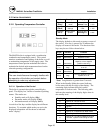
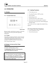
High Fire Setting
Set boiler to the “Test Mode High”, as described
above, to achieve maximum firing rate of the boiler.
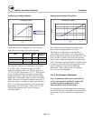
Check combustion readings using a combustion
analyzer. If combustion readings are not in
accordance with Table 3-1, adjust as follows:
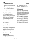
Remove the flat, round, blue plastic cap from the
cover. Using a 3mm (7/64”) hex wrench, turn the
adjustment screw counterclockwise to increase or
clockwise to decrease gas flow and achieve the desired
CO
2
or O
2
level; see Table 3-1 for correct settings.
(There will be a slight time delay between the
adjustment and the response of the CO
2
/O
2
measuring
instrument. Adjust the settings in small increments and
allow the combustion readings to stabilize before
readjusting. When desired adjustments are complete,
reinstall the blue plastic cap on the cover.
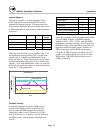
Low Fire Setting
Set boiler to the “Test Mode Low”, as described
above, to achieve minimum firing rate of the boiler.
Check combustion readings using a combustion
analyzer. If combustion readings are not in
accordance with Table 3-1, adjust as follows:
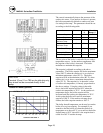
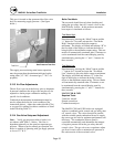
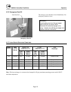
Remove the cap on the gas regulator using a slotted
screwdriver (See Fig. XX). This will expose the offset
adjustment screw.
Using a TORX® T40 or a 5 mm hex wrench, carefully
adjust the low fire gas setting to achieve the CO
2
/O
2
level prescribed in Table 3-1.
Note: The rotation of the Low Fire adjustment is
opposite of the High Fire as follows: Clockwise
rotation increases gas flow, counterclockwise rotation
decreases gas flow.
Adjustments to the offset pressure regulators should
not exceed ¼ turn at a time before allowing the
readings to respond and stabilize.
After proper low fire offset adjustment is made,
reinstall the slotted cap on the regulator.
Following all gas valve adjustments, check for proper
light-off and verify correct fuel/air mix and
combustion quality throughout the entire firing range
(from lowest to highest fan speed).
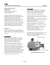
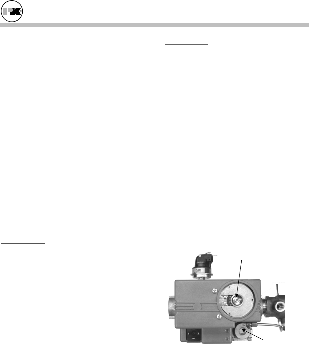
C750/900/10500 Adjusting Low and High
High fire adjustment
Low fire adjustment