


MACH® Series
Gas-Fired Boiler Installation
Page 10
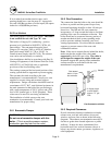
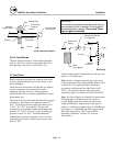
3.6.6 Sealed Combustion Air/Venting System
The MACH Series Boilers are also certified for
operation with a sealed combustion air and pressurized
venting system. Such a system employs a sealed
combustion air intake duct leading from outdoors and
a sealed exhaust vent terminating outdoors. Air flow
through the system is maintained by the fan inside the
boiler assembly.
Vent Installation Details
Installation must conform to the vent manufacturer's
instructions in all respects including joining,
clearances, fastening, fire-stopping, and other matters.
Vent ductwork may be run horizontally or vertically if
so certified.
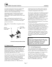
3.6.7 Removing an Existing Boiler
(from a common venting system)
When an existing boiler is removed from a common
venting system, the common venting system is likely
to be too large for proper venting of the appliances
remaining connected to it.
At the time of removal of an existing boiler, while the
other appliances remaining connected to the common
venting system are not in operation, the following
steps should be followed with each appliance
remaining connected to the common venting system
placed in operation:
1. Seal any unused openings in the common venting
system.
2. Visually inspect the venting system for proper size
and horizontal pitch and determine that there is no
blockage or restriction, leakage, corrosion or other
deficiency which could cause an unsafe condition.
3. Insofar as is practical, close all building doors
and windows and all doors between the space in
which the appliances remaining connected to the
common venting system are located and other
spaces of the building. Turn on clothes dryers
and any appliances not connected to the common
venting system. Turn on any exhaust fans, such
as range hoods and bathroom exhausts, so they
will operate at maximum speed. Do not operate a
summer exhaust fan. Close fireplace dampers.
4. Place the appliance being inspected in operation.
Follow the lighting instructions. Adjust the
thermostat so that the appliance will operate
continuously.
5. Test for spillage at the draft hood relief opening
after 5 minutes of main burner operation. Use the
flame of a match or candle or smoke from a
cigarette, cigar or pipe.
6. After it has been determined that each appliance
remaining connected to the common venting
system properly vents when tested as outlined
above, return doors, windows, exhaust fans,
fireplace dampers and any other gas-burning
appliance to their previous conditions of use.
Any improper operation of the common venting
system should be corrected so the installation
conforms with the National Fuel Gas Code, ANSI
Z223.1 and CSA B149 Installation Code. When
resizing any portion of the common venting system,
the common vent system should be resized to
approach the minimum size as determined using the
appropriate tables.
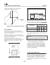
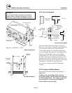
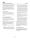
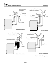
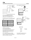
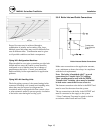
3.6.8 Intake/Exhaust Layout
Four basic configurations for the intake/exhaust may
be used. Refer to Section 3.6.3 for required
clearances for all terminations shown in the four
following figures.