


3
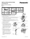
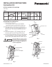
B. 18000 BTU and 24000 BTU inverter models
(1) Remove the air intake grille.
(2) Remove the terminal cover. Pull out the thermistor, then remove the grille.
For details on steps (1) and (2), refer to the Installation Instructions included in
the outdoor unit package.
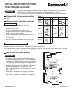
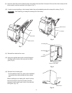
(3) Disengage the top cover from the tabs on the sides of the component box, then
pull the cover toward you to remove it. (Fig. 1)
(To disengage the tabs, pull the sides of the top cover sideways and outward
from the component box.)
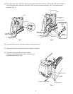
(4) Disconnect the indicator-side connector (10P) of the wires that connect the indi-
cator and component box (Fig. 2a). Then disconnect the connector on the com-
ponent box side (10P) and remove the wires. (Lifting the P.C. board up slightly
will make this work easier.) (Fig. 2b)
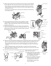
(5) After removing the wires, insert Connector 1 of the wires (Fig. 3a) that were
included in the kit package into the indicator (Fig. 2a), then insert Connector 2
into the component box. (Fig. 2b)
At this time, pass the wires through so that they are held inside the 2 holders on
the sides of the component box. (Fig. 3b)
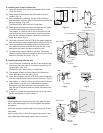
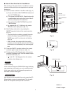
(6) Feed the wire harness that was included
in the wired remote controller package
into the right lower rear of the unit. (Fig. 4a)
Be careful not to damage the wire harness when installing the conduit during
unit installation work.
(7) Pass the wire harness through the wire tube that was included in the kit package.
Then connect Connector 3 (Fig. 3a) to the wire harness connector (4P). (Fig. 4c)
(8) Take the wires (Fig. 3a) and use a wire clamp to bind together the wire for the
noise filter and the wire for the thermistor (Fig. 5a). Then position them so that
the noise filter is contained within the space of the component box. (Fig. 5b)
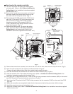
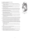
(9) Pass the wire tube through the clamping strap, and temporarily fasten in place
with the screw. Next, use a clamp and bind the wires together immediately above
the clamping strap, and fasten in place with the screw in order to prevent pulling
on the wire harness. (Fig. 6a)
Install the wire tube so that the wires cannot be damaged by the edge of the
metal plate. (Fig. 6a)
When re-installing the grille, confirm that there is no slack in the wire harness
wires.
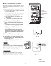
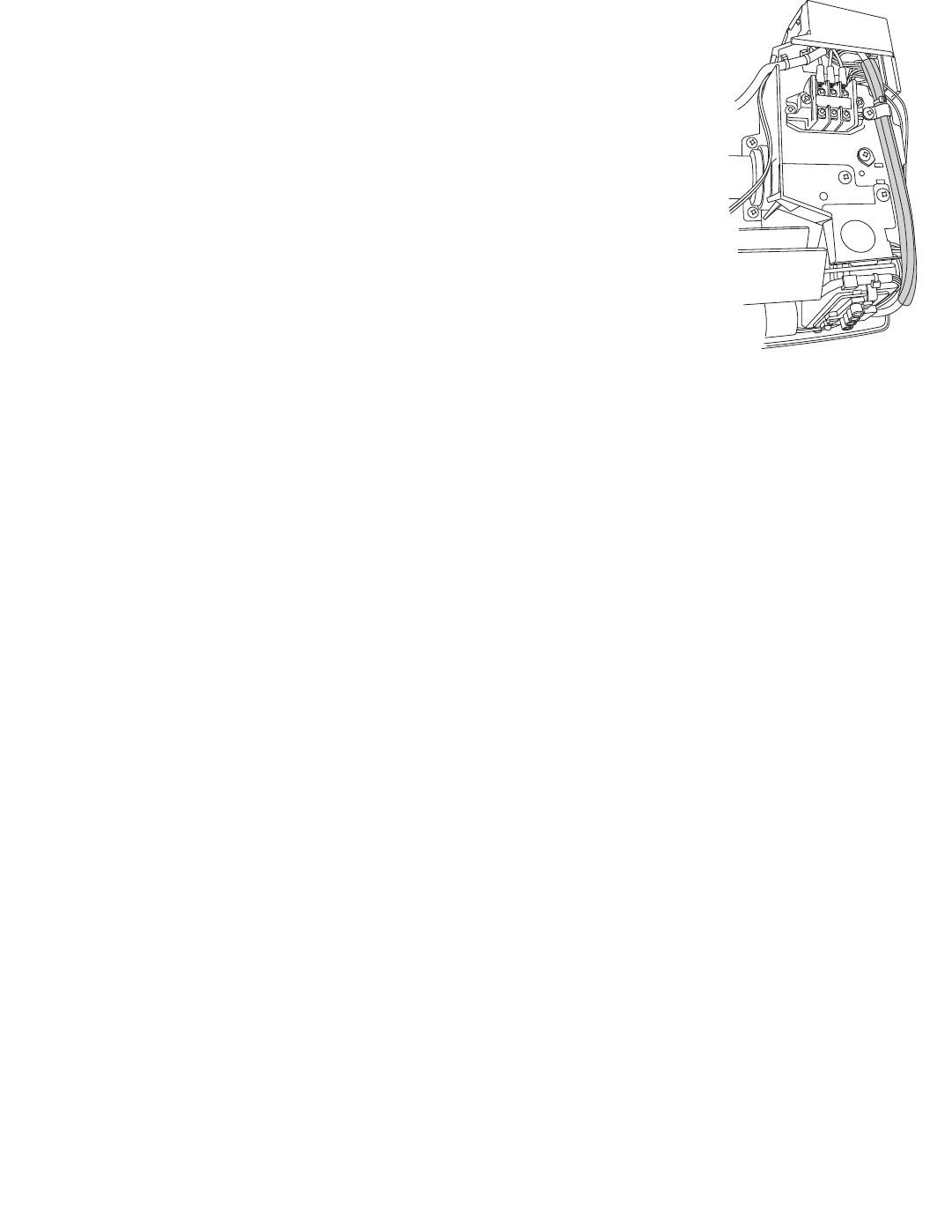
(10) Install the top cover on the component box. (Fig. 8)
(
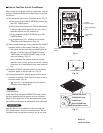
11) Route the wire harness out through the small cut-out located at the bottom right
side of the indoor unit frame. (Fig. 7a)
(12) Apply the label that was included in the package at a location close to the self-
diagnostic label applied to the air intake grille. (Fig. 7b)
(13) Refer to the Installation Instructions that were included in the outdoor unit pack-
age and re-install the grille, thermistor, terminal cover, and air intake grille.
Fig. 8
< Completion drawing >