Installing the connection kit
A. 7000 BTU, 9000 BTU, and 12000 BTU inverter models
(1) Remove the air intake grille.
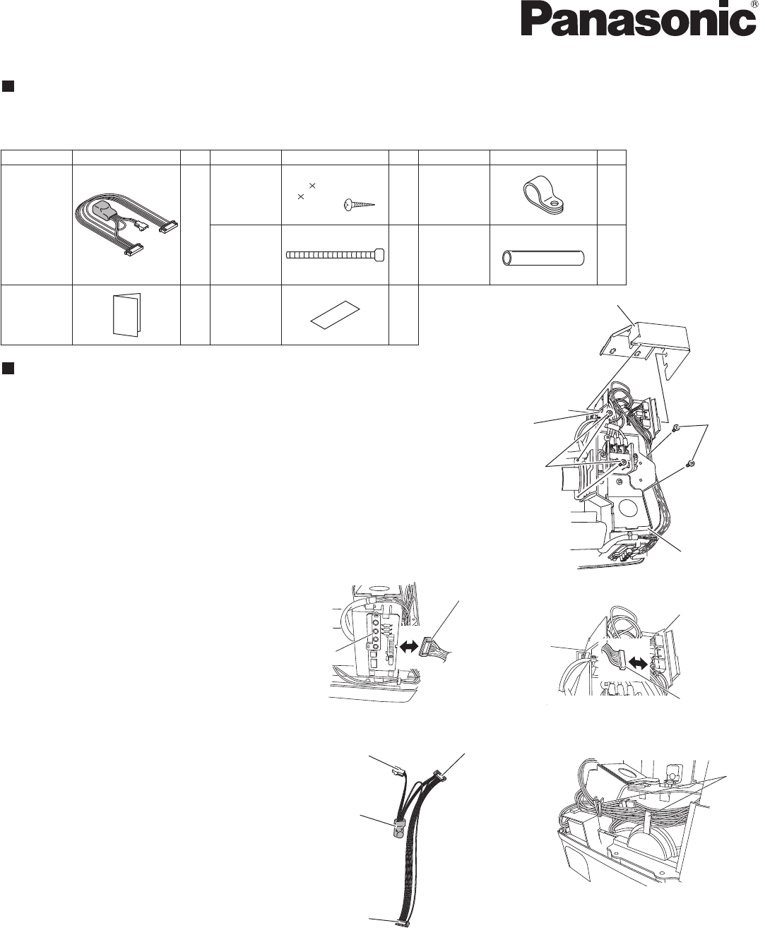
(2) Remove the terminal cover. Pull out the thermistor, then remove the grille.
For details on steps (1) and (2), refer to the Installation Instructions
included in the outdoor unit package.
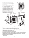
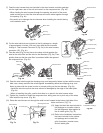
(3) Disengage the top cover from the tabs on the sides of the component
box, then pull the cover toward you to remove it. (Fig. 1)
(To disengage the tabs, pull the sides of the top cover sideways and out-
ward from the component box.)
(4) Remove the 4 component box
installation screws. (Fig. 1)
(5) Disconnect the indicator-side connec-
tor (10P) of the wires that connect the
indicator and component box (Fig. 2a).
Then disconnect the connector on the
component box side (10P) and remove
the wires. (Lifting the P.C. board up
slightly will make this work easier.)
(Fig. 2b)
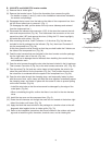
(6) After removing the wires, insert
Connector 1 of the wires (Fig. 3a) that
were included in the kit package into
the indicator (Fig. 2a), then insert
Connector 2 into the component box.
(Fig. 2b)
At this time, pass the wires through so
that they are held inside the 2 holders
on the sides of the component
box.
(Fig. 3b)
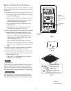
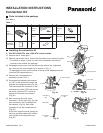
Parts included in the package
See Table 1.
Table 1
P.C. board
Connector (10P)
Fig. 2b
Connector 2
(10P)
Connector 1
(10P)
Connector 3
(4P)
Noise filter
Fig. 3a
Holder
Fig. 3b
Parts Figure Q'ty Parts Figure Q'ty Parts Figure Q'ty
Clamp
Label
Installation
instructions
Wire
(with a
noise filter)
Clamping
strap
Wire tube
1
2
1
1
1
1
1
Tapping
screw
Truss-head Phillips
5/32 13/32"
(4 10
mm
)
7-3/32"(180
mm
)
Component box
Screw
Screw
Top cover
Tab
Fig. 1
Indicator
Connector (10P)
Fig. 2a
Connection Kit
85264190590000 2011
INSTALLATION INSTRUCTIONS
CV6233187907


