


25
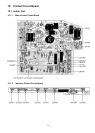
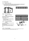
11.2 Indoor Unit
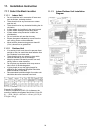
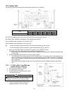
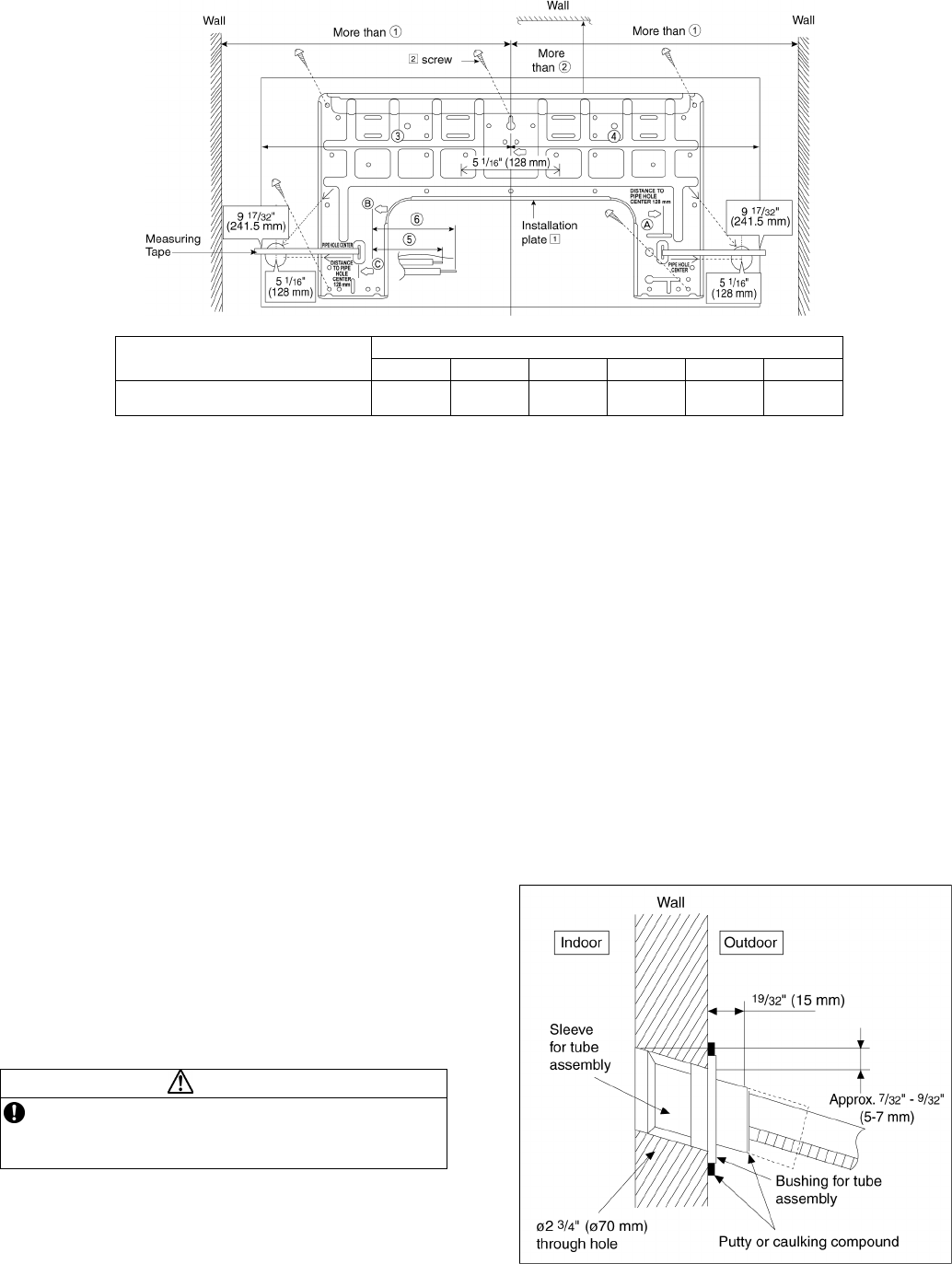
The mounting wall shall be strong and solid enough to prevent it from vibration.
Model
Dimension
c d e f g h
XE9PKUA, XE12PKUA
19-9/32"
(490 mm)
3-7/32"
(82 mm)
17-9/32"
(439 mm)
17"
(432 mm)
1-11/16"
(43 mm)
3-3/4"
(95 mm)
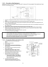
The center of installation plate should be at more than
○
1 at right and left of the wall.
The distance from installation plate edge to ceiling should more than
○
2.
From installation plate left edge to unit’s left side is
○
3.
From installation plate right edge to unit’s right is
○
4.
○
B : For left side piping, piping connection for liquid should be about
○
5 from this line.
: For left side piping, piping connection for gas should be about
○
6 from this line.
1 Mount the installation plate on the wall with 5 screws or more (at least 5 screws).
(If mounting the unit on the concrete wall, consider using anchor bolts.)
o Always mount the installation plate horizontally by aligning the marking-off line with the thread and using
a level gauge.
2 Drill the piping plate hole with ø2-3/4" (ø70 mm) hole-core drill.
o Line according to the left and right side of the installation plate. The meeting point of the extended line is
the center of the hole. Another method is by putting measuring tape at position as shown in the diagram
above. The hole center is obtained by measuring the distance namely 5-1/16" (128 mm) for left and right
hole respectively.
o Drill the piping hole at either the right or the left and the hole should be slightly slanting to the outdoor
side.
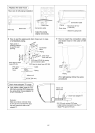
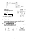
11.2.1 To Drill a Hole in the Wall and
Install a Sleeve of Piping
1 Insert the piping sleeve to the hole.
2 Fix the bushing to the sleeve.
3 Cut the sleeve until it extrudes about 19/32"
(15 mm) from the wall.
CAUTION
When the wall is hollow, please be sure to use the
sleeve for tube assembly to prevent dangers
caused by mice biting the connection cable.
4 Finish by sealing the sleeve with putty or
caulking compound at the final stage.