


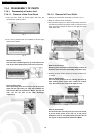
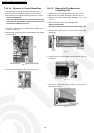
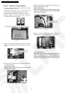
13.4.2.4. Removal of Control Board
1. Remove the Cabinet Top Plate and Cabinet Front Plate
according to the item 13.5.2.1.
2. Remove the Power Supply Cover (2- / 3-way valve Covers
and Terminal Cover) according to the item 13.5.2.2.
3. Remove the Control Plate Casing according to 13.5.2.3.
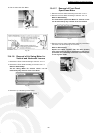
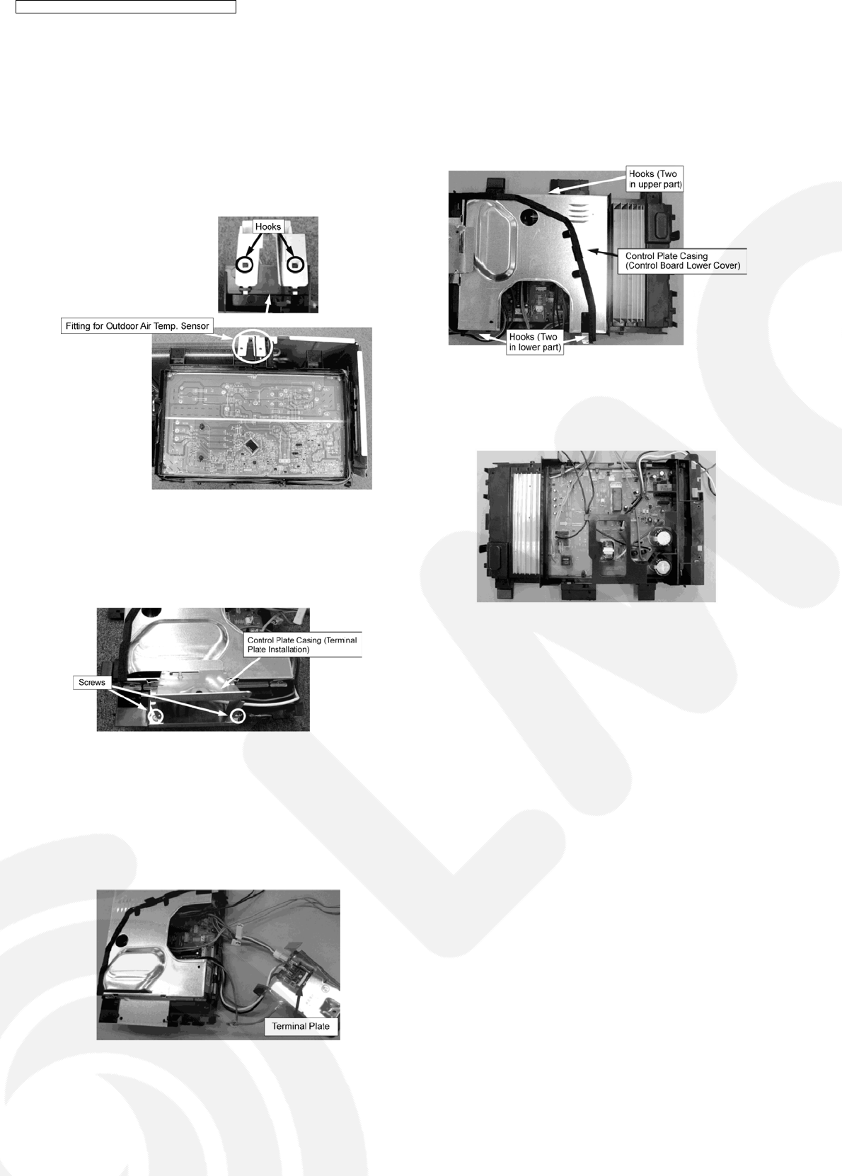
4. Remove Outdoor Air Temp. Sensor and its fitting by
releasing the hooks (two) the fitting.
Fig. 9
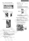
5. Place the Control Box reversely and remove the Screws
(Two) on the both sides of the Control Box (for Terminal
Plate).
Fig. 10
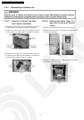
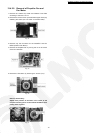
6. Remove the Control Plate Casing (Terminal Plate) from the
Control Plate Casing.
Note for Disassembly:
Remove Power supply terminal (red, white and black)
from the Terminal Plate.
Fig. 11
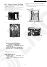
7. Remove the Control Box by releasing the hooks (four) the
Box (Control Board Lower Cover).
Note for Disassembly:
Be careful of hanging-up of connectors or wiring cables
such as the earth wire when the Box (Control Board
Lower Cover) is removed.
Fig. 12
8. Replace the Control Plate Casing (Black plastic part)
together when the Control Board needs to be replaced.
Fig. 13
Note for Disassembly:
Replacement of the Outdoor Control Board should be
made as a whole unit due to silicon pasting, etc.
although it can be separated PCB part from Control Box
part by removing the screws (six) on the soldering side.
72
CS-TE9DKE CU-TE9DKE / CS-TE12DKE CU-TE12DKE