


4
TEST
RESET
HOW TO USE THE A.L.C.I
1
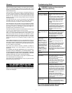
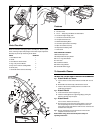
Parts Checklist
Read all instructions thoroughly before assembly/use. Please unpack
carton, removing all parts and packages. Check that all parts required for
assembly are present by referencing the list below.
PARTS QUANTITY
1. Oreck Steemer Unit 1
2. Handle 1
3. Oreck Steemer Power Nozzle 1
4. Large, easy-to-steer Wheels 2
5. Easy Lock-in Cleaner Cartridge/Bottle 1
6. Screws (5/8”) 4
7. Hand-held Nozzle and Hose Assembly 1
2
3
4
5
6
8
9
19
20
21
22
23
10
11
12
13
14
15
18
16
Features
8. 25’ Power Cord
9. A.L.C.I. – Safety Plug with Reset and Test Buttons
10. Translucent Upper Supply Tank
11.Translucent Lower Recovery Tank
12. Transparent Nozzle Cover
13. Motorized Scrubbing Brush
14. Convenient quick-release Cord Wrap
15. Wiper for hard floor cleaning
16. Temperature Indicating Label
17. Floor Stand
RED OPERATOR CONTROLS
18. Rinse/Shampoo Valve
19. Shampoo/Cleaner Spray Button
20. A.L.C.I. Plug Reset Button
21. Tank Latch
22. On/Off Power Switch
23. Nozzle Change Button
24. Hand-held Nozzle Trigger
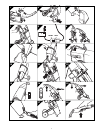
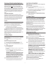
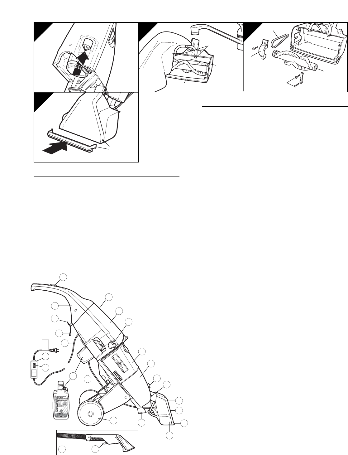
To Assemble Cleaner
THE ONLY TOOL YOU WILL NEED IS A PHILLIPS-TYPE SCREWDRIVER!
fig. 1 Attach Handle to Cleaner:
a. Lay the cleaner on a flat surface with the tank side down or to its
side.
b. Slide handle into cleaner body until interlock is secured.
c. Insert four 5⁄8” screws (included) into the four cavities in the
handle base and tighten.
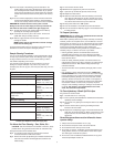
fig. 2
Attach Wheels:
a. Locate two wheels and two support legs.
b. Insert the wheels (a) into the support legs (b) by pushing the
wheels in until they snap into place.
fig. 3
Attach Nozzle:
Turn the unit so that the tank is face up.
a. Align the nozzle so the red nozzle change button is in line with
the corresponding hole in the nozzle. Depress the small red
nozzle change button and slide the nozzle over the unit shaft until
the button locks into place.
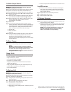
fig. 4 Plug the small power cord connected to the nozzle into the
receptacle in the back of the unit.
NOTE: Before using, please read the important safety and
operating instructions.
17
19 20 21
c
b
a
7
24
a
b
c
d
22
a