


19
General Parts Replacement
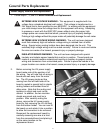
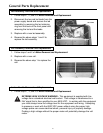
Power Supply Removal and Replacement
1. Follow steps 1, 3, and 6 of Motor Removal and Replacement.
EXTREME HIGH VOLTAGE WARNING - This equipment is supplied with line
voltage from a standard electrical wall socket. That voltage is transformed to a
24V signal that is then amplified to over 6000VDC. In working with the equipment
you must always know the voltage level for the equipment and wiring. Attempting
to measure or work with the 6000 VDC power without using the proper high
voltage probe can cause electrical shock, personal injury or property damage.
Probing a high voltage without the proper meter will potentially damage the volt meter.
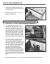
EXTREME HIGH VOLTAGE WIRING WARNING - The unit has been designed
such that extremely high cell collector voltage wiring is isolated from all other
wiring. Special wiring routing holders have been designed into the unit. This
extremely high voltage wiring must be routed correctly. Failure to route and isolate
the wire can create a fire hazard, personal injury or property damage.
INSULATOR BOARD WARNING - The unit has been designed with special
insulator and isolator spacer boards that must be in position. These boards are
made of a special insulator material and must be in position to properly isolate
wiring and connectors from uninsulated parts. Failure to place the boards in the
proper location can create a fire hazard, cause personal injury, or property damage.
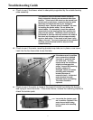
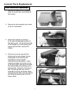
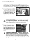
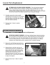
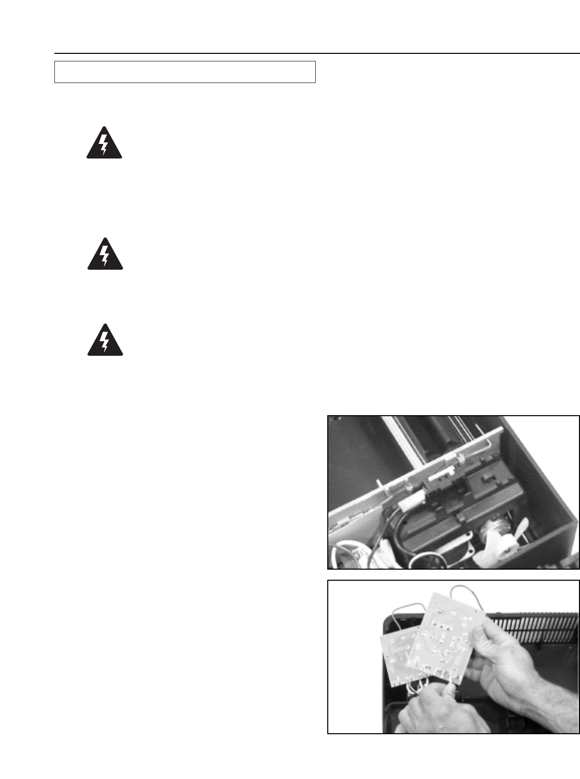
2. Before removing the HV power supply
board make note of the position of all
the wiring. You will note that all wiring is
bound and well away from the motor
fan. The HV power single red line
coming from the left hand side of the
board is routed in special built-in plastic
routing holders and isolated from all
other wires. Note that the routing and
isolation is critical and must not be
altered. In addition, the two insulator
sheets are preset and must be in
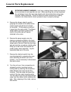
position. After carefully noting the
above, remove the HV power supply
board by first removing the HV red lead
from the bottom holder. You can now lift
the board up and rotate it into a position
to allow the connectors to be removed.
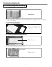
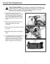
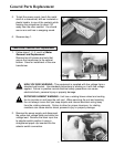
Reconnect the replacement board by
carefully removing one wire at a time
from the connected board and placing it
on the same location on the
replacement board.