


6
4 ELECTRICAL INSTALLATION
Warning. Before making any
connections, ensure that the power
supply, any high voltage-operated control
circuits and high common mode voltages
are switched off.
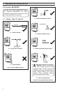
Note.
• Always route signal leads and power
cables separately, preferably in
earthed metal conduit.
• It is strongly recommended that
screened cable is used for signal
inputs and relay connections. Connect
the screen to the ground stud.
Information. Use cable appropriate
for the load currents. The terminals accept
cables up 12AWG (2.5mm
2
).
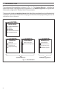
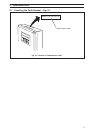
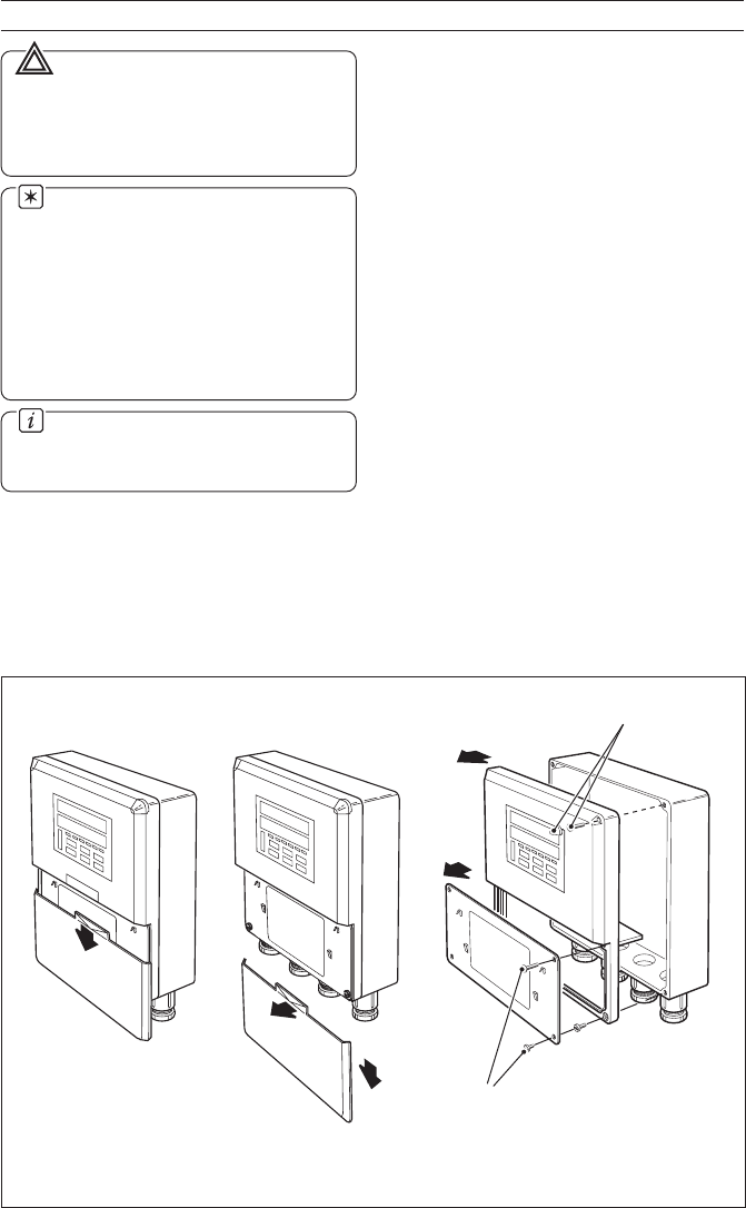
4.1 Access to Terminals – Fig. 4.1
For access to terminals – refer to Fig. 4.1,
steps 1 to 3.
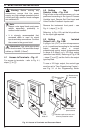
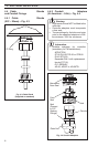
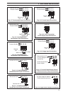
4.2 Setting the Input
Selector Links – Fig. 4.2A
Plug-in links on the microprocessor p.c.b. are
positioned according to the type of Process
Variable Input, Remote Set Point Input and
Valve Position Feedback Inputs used.
Remove the instrument front panel – see
Fig. 4.1, steps 1 to 6.
Referring to Fig. 4.2A, set the link positions
for the input type required.
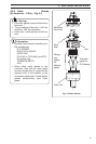
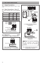
4.3 Setting the Isolated
Output Link – Fig. 4.2B
A plug-in link (PL7) on the microprocessor
p.c.b. is positioned according to the isolated
output required, either a current
proportioning control output (programmable
in range 0 to 20mA) or a 12V logic output
(minimum load 400Ω). Referring to Fig. 4.2B
– steps 1 and 2, set the link for the output
type required.
To use a 12V logic output, the control type
must be set to Time Proportioning Control –
see Fig. 3.1
of the Programming Guide
.
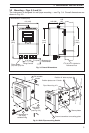
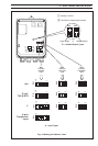
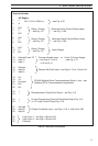
Fig. 4.1 Access to Terminals and Processor Board
Slacken captive screws and
remove protection cover
Remove front
panel screws
Remove front
panel
Remove cap
and screw
4
6
slide
down
1
Pull out
slightly…
…and
slide off
2
2
5
3