


12
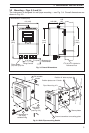
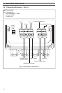
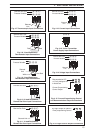
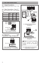
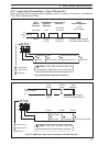
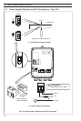
4.6 Input Connections
Make connections to each input, as shown in Figs 4.4 to 4.14, first removing any factory-fitted
wire links not required.
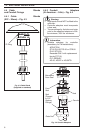
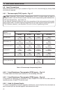
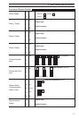
4.6.1 Thermocouple (THC) Inputs – Fig. 4.7
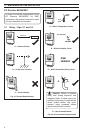
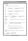
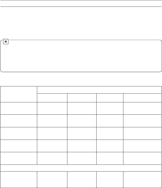
Note. Automatic Cold Junction Compensation (ACJC) is active when an input is
programmed for use with thermocouples. Use the correct compensating cable between the
THC and the terminals – see Table 4.2.
If an external fixed cold junction is used, the connections to the instrument must be made
with copper cable. The input must be programmed for mV input signals and the appropriate
THC linearizer selected – see Sections 4.5 and 4.6 of the
Programming Guide.
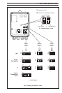
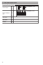
Table 4.2 Thermocouple Compensating Cables
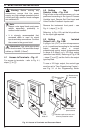
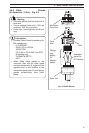
4.6.2 3-lead Resistance Thermometer (RTD) Inputs – Fig. 4.8
The three leads must have equal resistance, not exceeding 50Ω each.
4.6.3 2-lead Resistance Thermometer (RTD) Inputs – Fig. 4.9
If long leads are necessary it is preferable to use a 3-lead RTD. If the RTD is to be used in a
hazardous area a 3-lead RTD must be used.
4.6.4 Links for Unused Inputs
To reduce susceptibility to electro-magnetic interference, ensure that the three terminals on
each unused input are shorted together with sleeved wire links.
…4 ELECTRICAL INSTALLATION
foepyT
elpuocomrehT
elbaCgnitasnepmoC
3481SB
ISNA
1.69CM
NID
41734
7394SB
03.oNtraP
)K(lA-iN/rC-iN
nworB+
eulB–
deResaC
wolleY+
deR–
wolleYesaC
deR+
neerG–
neerGesaC
neerG+
etihW–
*neerGesaC
)N(lisiN/lisirciN
egnarO+
eulB–
egnarOesaC
egnarO+
deR–
egnarOesaC
—
kniP+
etihW–
*kniPesaC
)SdnaR(hR-tP/tP
etihW+
eulB–
neerGesaC
kcalB+
deR–
neerGesaC
deR+
etihW–
etihWesaC
egnarO+
etihW–
*egnarOesaC
)T(iN-uC/uC
etihW+
eulB–
eulBesaC
eulB+
deR–
eulBesaC
deR+
nworB–
nworBesaC
nworB+
etihW–
*nworBesaC
)J(noC/eF
wolleY+
eulB–
kcalBesaC
etihW+
deR–
kcalBesaC
deR+
eulB–
eulBesaC
kcalB+
etihW–
*kcalBesaC
stiucricefasyllacisnirtnirofeulBesaC*
)01734NID(noC/eF ——
01734NID
der/eulB+
eulB–
eulBesaC
—