


14
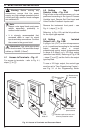
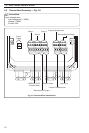
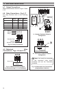
4.7 Output Connections
Make connections as shown in Figs 4.15 and
4.16.
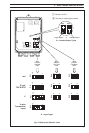
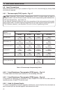
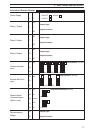
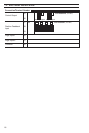
4.8 Relay Connections – Fig. 4.17
For relay functions refer to the following
table.
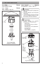
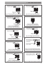
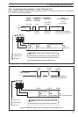
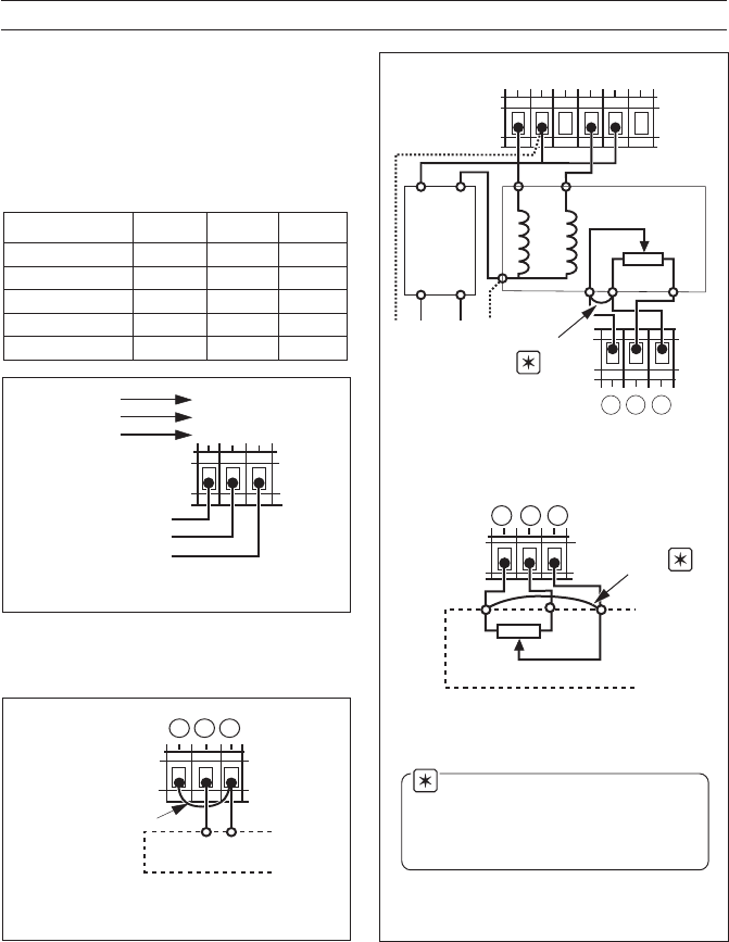
A – Standard Feedback Slidewire
Configuration
B – Alternative Feedback Slidewire
Configuration
Note. Link must be connected
at the motorized valve drive
terminals and not the Controller
terminals.
…4 ELECTRICAL INSTALLATION
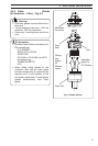
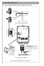
0%
100%
Motorized Valve Drive
27 2928
Link
Fig. 4.19 Motorized Valve Connections
(using feedback slidewire)
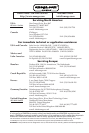
4.9 Motorized Valve
Connections – Figs. 4.18 and 4.19
43
76
09
5
8
!
Relay 3
Relay 2
Relay 1
Normally Closed
Common
Normally Open
Fig. 4.17 Relay Connections
2927 28
Motorized Valve
Drive
–
Sleeved Link
+
Fig. 4.18 Motorized Valve Feedback
Connections (using V, I or mV feedback)
1yaleR2yaleR3yaleR
lortnoCffO/nO
✓
——
)taeH(.porPemiT
✓
——
)looC(.porPemiT
—
✓
—
evlaVdezirotoM nepOesolC
—
mralA
✓✓✓
7
8
(N)
N
L
(L)
Motorized
Valve Drive
Valve
Positioner
Power
Supply
0%
100%
5
6
3
4
100%
Link
0%
29
27
28