


4
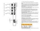
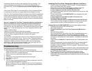
General purpose, dry
contact input
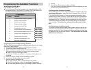
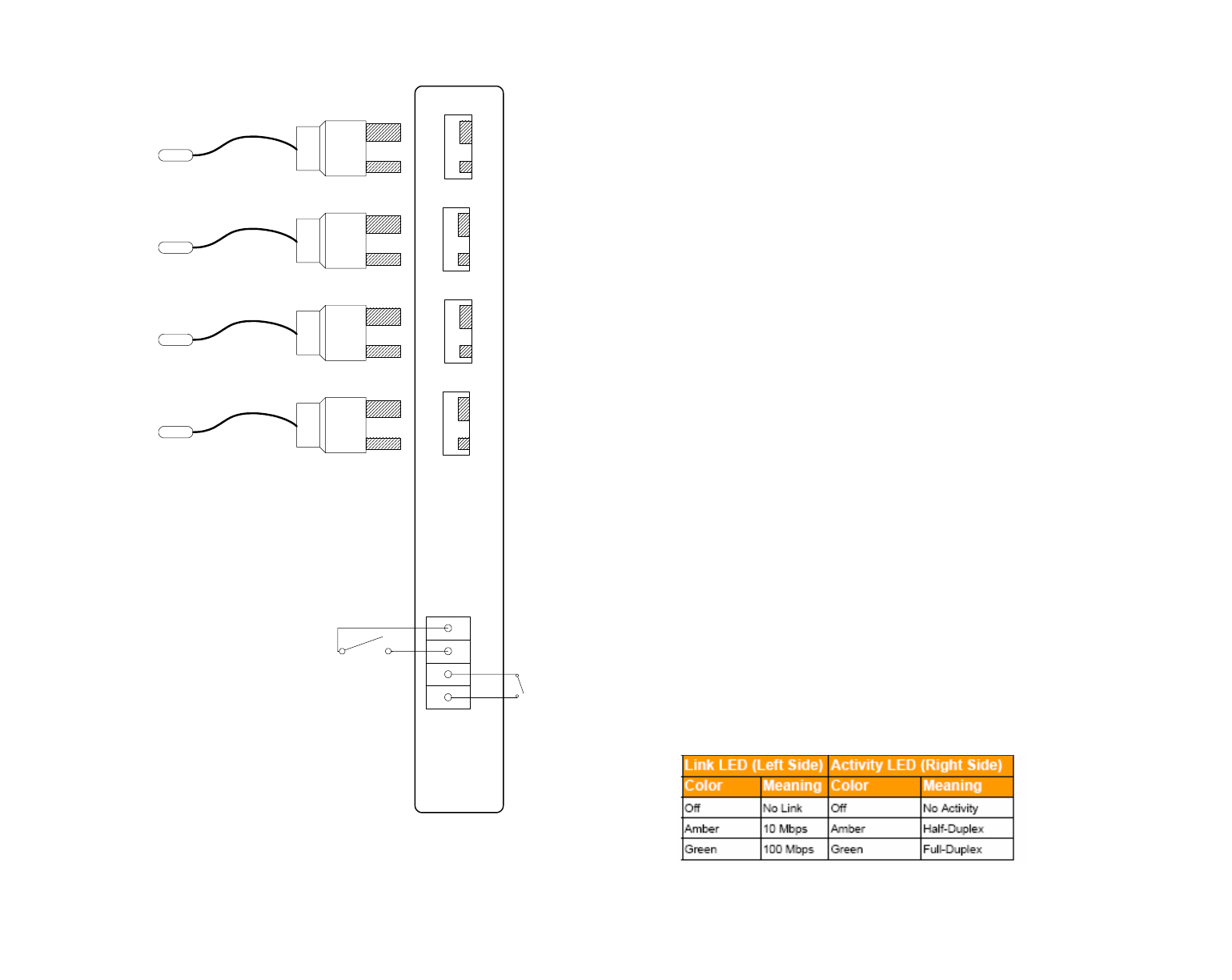
Wiring Diagram
Alarm Relay Output
Plug in Thermocouple Terminals
1234
K +
K +
K +
K +
Sensor 1 Sensor 2 Sensor 3 Sensor 4
K
+
K
+
K
+
K
+
K type thermocouples with integrated spade connectors
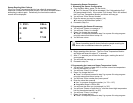
8 Watch the display and note any messages present.
If the Four Zone Temperature Monitor and Alarm does not answer the
phone
Verify that the phone line is a standard analog telephone line. Digital phone
lines are not compatible with the Four Zone Temperature Monitor and Alarm.
Verify that the phone line is working. Connect a standard phone to the line
intended for the Four Zone Temperature Monitor and Alarm. Verify that
there is a dial tone.
Check that the phone line is plugged in securely.
Verify that the Four Zone Temperature Monitor and Alarm is powered up and
some data a is being displayed on the display.
If the Four Zone Temperature Monitor and Alarm does not call out
Perform the telephone communication verification procedure. Connect a
phone to the line intended for the Four Zone Temperature Monitor and
Alarm. Verify that there is a dial tone.
Check that the phone line is plugged in securely
Verify that the Four Zone Temperature Monitor and Alarm is powered up and
the status light is blinking
Verify that the Four Zone Temperature Monitor and Alarm is programmed
correctly. Call up the Four Zone Temperature Monitor and Alarm and verify
the programmed phone numbers and limits.
Optional 20 / 30 Hour Extended Batteries
If your unit has been ordered with an extended battery, it is installed at the
factory and is inside the OMA-VM520.
Standard 4 hour / 20 / 30 Hour Batteries
The rechargeable batteries used in the Four Zone Temperature Monitor are
trickle charged and can take up to a week to reach full capacity. The batter-
ies are charging whenever the monitor is powered on.
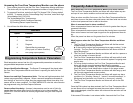
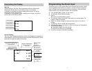
Verifying Network Connectivity (DCP units)
When first plugging in the unit or connecting the LAN cable, the LEDs on the
Ethernet jack will begin to blink first orange and then green. When fully
powered up the left LED will be on steady green and the right LED will blink
green.
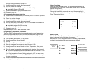
Accessing advanced network setup
To set either the Subnet Mask or Gateway Address of the device, access the
advanced network setup by entering:
21