


9
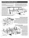
Use the following procedures for installation in existing construction.
Starting from farthest wall inlet location, install each inlet as described
below. Working back toward power unit, connect each inlet line and
branch line into main trunk line. See page 5. Complete low voltage wiring
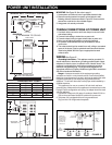
as main trunk line is continued back to power unit. Mount power unit and
complete wiring. See page 8.
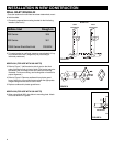
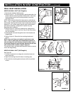
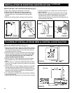
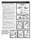
1. See Figure 29. A small ‘pilot’ or ‘locating’ hole can be drilled behind
baseboard toe strip to determine proper location of 2
1
⁄2" diameter tubing
hole in sole plate.
2. Measure the total thickness of the wall, including baseboard. One half of
this wall thickness measured from the pilot hole (dimension ‘X’) will
determine the proper location of the 2
1
⁄2" tubing hole in the sole plate.
3. Once desired inlet locations have been determined, cut a 2
1
⁄2" hole in
sole plate directly in line with proposed inlet location. Check through
tubing hole to be sure no obstruction exists.
4. Be sure tubing hole is centered in sole plate and directly in line with
proposed wall inlet cutout.
BASEBOARD
TOE STRIP
PILOT HOLE
“X”
SOLE PLATE
FIGURE 28
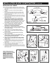
NOTE: If 330 Wall Inlet is being used refer to Model 330 Wall Inlet
Installation on next page.
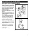
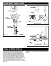
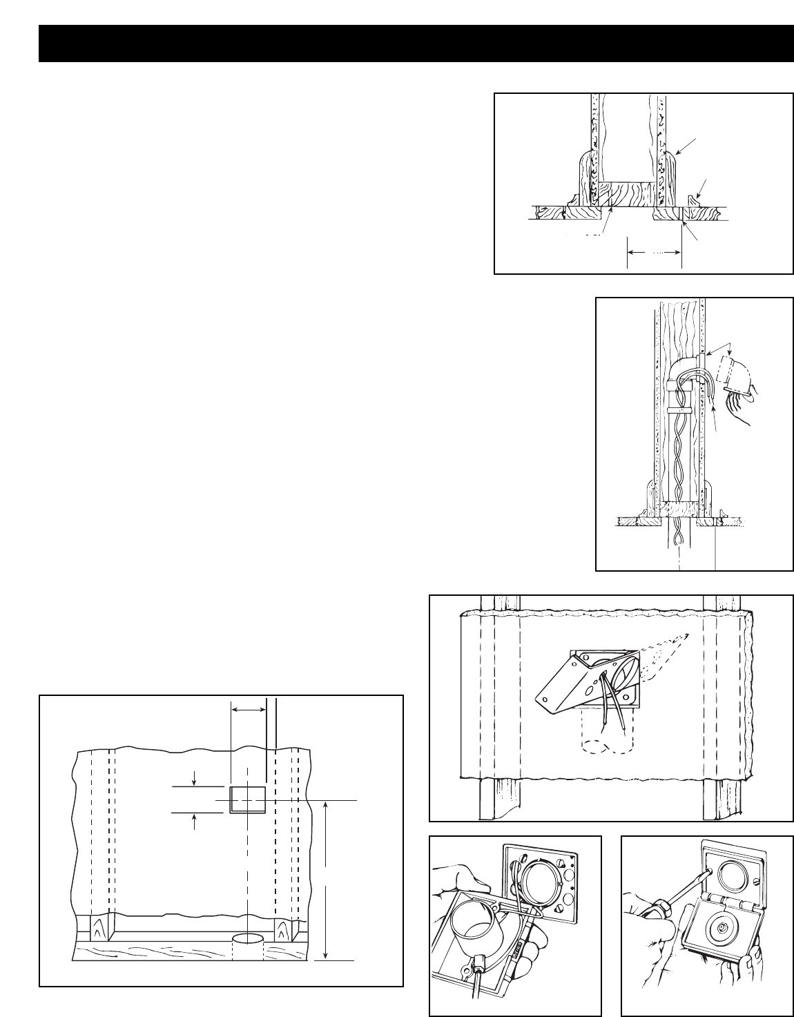
5. If area is clear, cut an inlet opening in the wall approximately 18" above the floor.
Make sure wall opening and 2
1
⁄2" tube hole line up (Figure 29).
6. Cut a length of tubing that will extend from inlet opening to a point below floor level
(or above ceiling level in attic installation). Tape low voltage wire to tube and insert tube
through predrilled hole to a level opposite the wall opening.
7. Apply cement to tube and install flanged wall fitting. Make sure fitting is well seated
and sealed (Figure 30).
8. Remove plaster frame from mounting bracket. Pull low voltage wire through hole in
bracket and insert bracket into cutout. Secure bracket to flanged fitting with four screws
provided. Be sure seal is secure between flange fitting and
mounting bracket (Figure 31).
9. Attach the low voltage wires to terminal screws on back of wall
inlet (Figure 32).
10. Insert wall inlet into bracket and secure with the two screws
provided (Figure 33).
2
1
/2"
2
9
/16 "
3
1
/16 "
18"
FIGURE 29
FIGURE 31
FIGURE 32 FIGURE 33
LOW
VOLTAGE
WIRING
FLANGED
FITTING
FIGURE 30
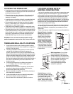
INSTALLATION IN EXISTING CONSTRUCTION
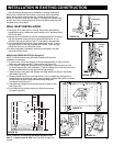
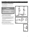
NOTE: If the wall for mounting the Model 360 inlet is less
than
1
⁄2", a spacer must be used. See Figure 20 on page 6 as
a guide.
WALL INLET INSTALLATION
MODEL 360 SERIES INLETS (361 Rough-In)