


6
INSTALLATION IN NEW CONSTRUCTION
(continued)
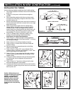
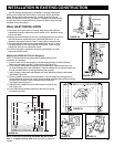
FIGURE 19
FIGURE 21
MODEL 365
DOUBLE FLANGED
TEE
WALL
INLET
MOUNTING
BRACKET
SHORTEN
WALL
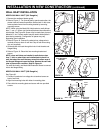
FIGURE 17
MODEL 360 WALL INLET (361 Rough-In)
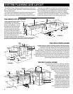
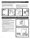
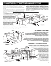
1. Remove the cardboard plaster guard.
2. Refer to Figure 17. For some drywall or panel construction, the
plaster frame will extend beyond the finished wall. In this case,
remove plaster frame from mounting bracket by removing
mounting screws.
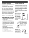
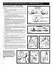
NOTE: When using the Model 361 inlet bracket on walls thinner
than
1
⁄2", use a
1
⁄4" spacer (not furnished) between the wall and the
inlet bracket. See Figure 20. Spacer may be made from plywood,
Masonite™, etc. Contact cement may be used to hold spacer in
place during assembly. Configuration of spacer may vary
depending upon installation.
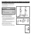
3. Refer to Figure 18. Connect 2-conductor low voltage wire to
terminal screws on back of wall inlet. Cap off both wires using
wire nut (supplied).
4. Guide excess wire back through the hole in inlet bracket and
flanged fitting
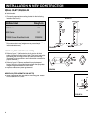
5. Refer to Figure 19. Place inlet into mounting bracket and
secure.
NOTE: when wall inlets are installed in walls that are less
than
1
⁄2" thick or when inlets are installed back-to-back in a
wall, the tube of the wall inlet may extend into elbow area of
the flanged fitting and cause blockage. Shorten the wall inlet
tube to prevent this condition. Refer to Figure 21.
For extra thick walls, use Model 399 Extension Sleeve to connect
inlet to the flanged fitting.
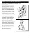
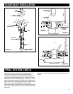
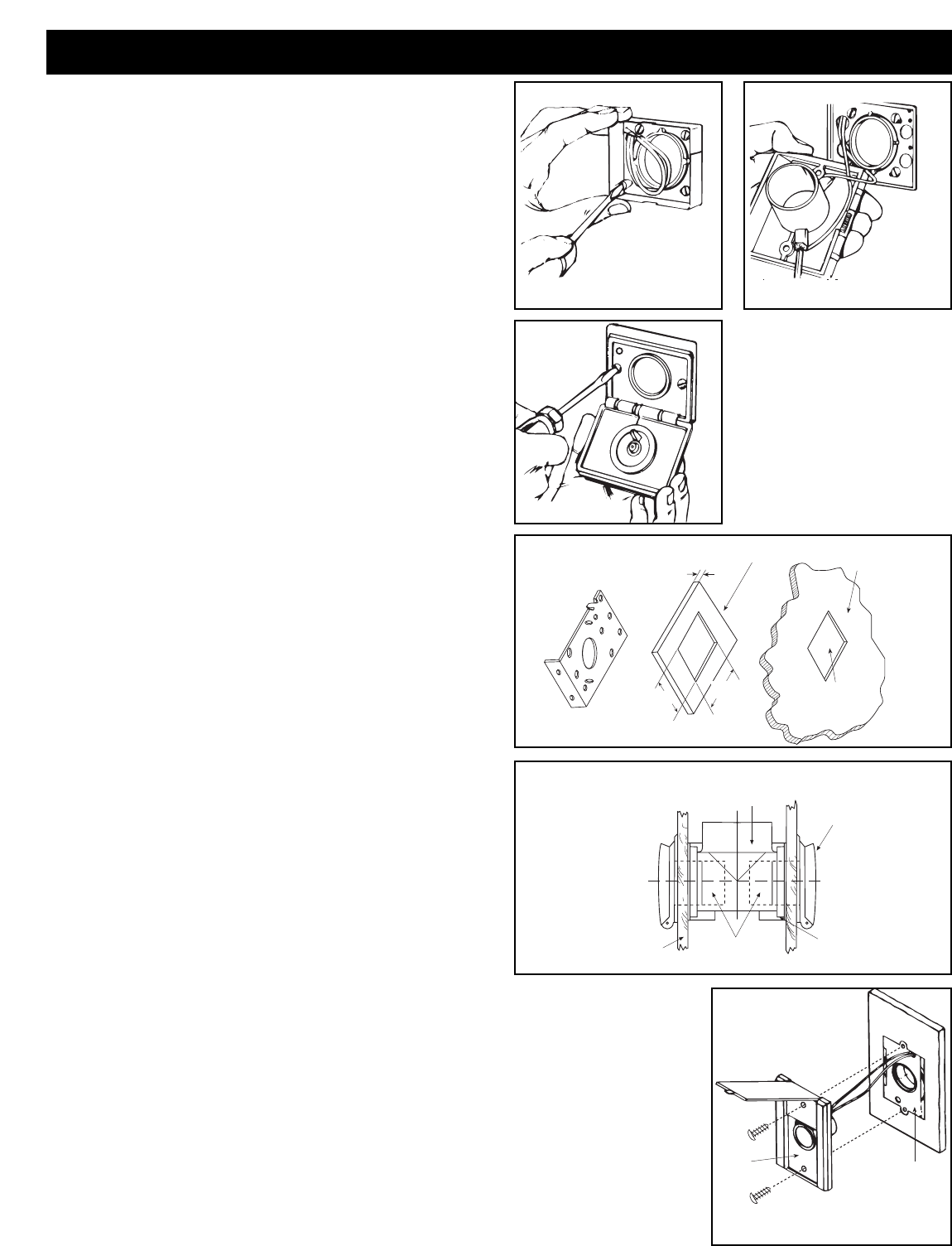
MODEL 330 WALL INLET (329 Rough-in)
See Figure 23.
1. Connect 2-conductor low voltage wire to terminal screws on
back of wall inlet.
2. Align inlet mounting holes with holes in mounting plate.
3. Place inlet into mounting plate and secure with two provided
screws.
MOUNTING
PLATE
INLET
FIGURE 22
WALL INLET INSTALLATION
2
1
/4"
3
1
/4"
1
/4"
INLET MOUNTING
BRACKET
SPACER
WALL LESS THAN
1
/2" THICK.
PLASTER
GUARD
HOLE
FIGURE 20
FIGURE 18