


10
INSTALLATION IN EXISTING CONSTRUCTION
(continued)
MOUNTING
PLATE
MOUNTING
HOLE (2)
ELBOW
FIGURE 36
MOUNTING
PLATE
INLET
FIGURE 37
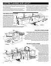
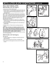
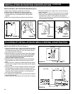
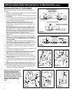
1. Make cutout according to dimensions in Figure 34.
2. Refer to Figure 35. Break off nail plate at scored line.
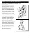
3. Refer to Figure 36. Glue elbow to mounting plate, place
assembly into cutout, and attach elbow to tubing inside
the wall.
4. Make sure mounting holes are exactly at top and bottom.
1
3
/8"
1
/4"
3
/8" DIA.
3
/8" DIA.
1
/4"
2
3
/4"
3
7
/8"
FIGURE 34 FIGURE 35
MODEL 330N WALL INLET INSTALLATION (329 Rough-in)
5. Connect 2-conductor low voltage wire to terminal screws on
back of wall inlet.
6. Refer to Figure 37. Align inlet mounting holes with mounting
plate holes, place inlet into mounting plate, and secure with
provided screws. NOTE: If 382-S shorter radius elbow is
used, it may be necessary to use the short mounting screw to
avoid interference with elbow.
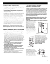
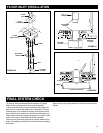
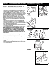
FLOOR INLET INSTALLATION IN NEW & EXISTING CONSTRUCTION
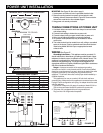
1. Refer to Figures 38 and 39. After floor inlet location has been
selected, cut a 3
1
⁄16" x 2
9
⁄16" square hole in floor. Center line of
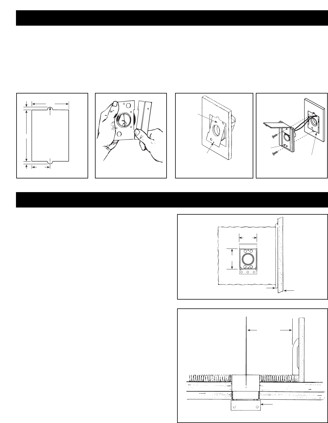
inlet must be located at least 2
1
⁄2" from wall to allow cover to
be opened when hose is inserted.
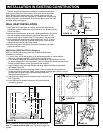
2. Determine direction of tubing and attach appropriate flanged
fitting to mounting bracket with four (4) screws supplied. Be
sure mounting bracket flange does not interfere with
tubing and seal is securely in place.
3. Refer to Figure 40. Position bracket with frame and flanged
fitting assembly into cutout from below and secure to sub
floor.
4. Refer to Figure 41. Large end of Model 399 extension sleeve
should be cut to length to allow proper seating of inlet against
floor or carpet.
5. Refer to Figure 42. Pull low-voltage 2-conductor wire through
mounting bracket and attach to terminal screws on back of
floor inlet. Cement extension sleeve to model 360 inlet. Insert
extension sleeve through vinyl gasket in mounting bracket
and firmly seat into flanged fitting.
6. For convenience of operation, floor inlet should be installed to
open back toward wall.
7. Refer to Figure 40. Secure floor inlet in place with two screws.
MOLDING
WALL
TOP VIEW
2
9
/16"
3
1
/16"
FIGURE 38
2
1
/2" MIN.
APPROX.
SIDE VIEW
MOUNTING BRACKET
FLANGE
FIGURE 39
MODEL 360 SERIES INLETS (361 Rough-in)