


23
A well designed and installed ducting system will allow
theHRV/ERV to operate at its maximum efficiency.
Always try to keep duct runs as short and straight as
possible.See Installation Diagrams for various instal-
lation options.
Outside Weatherhoods
The fixed covered hoods have a built-in bird screen
with a 1/4" (6 mm) mesh to prevent foreign objects
from entering the ductwork.
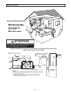
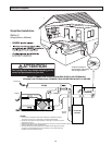
Locating the Intake Weatherhood
• Should be located upstream (if there are prevail-
ing winds) from the exhaust outlet
• At least 6' (2 m) from the exhaust weatherhood
• At least 6' (2 m) away from dryer vents and fur-
nace exhaust (medium or high efficiency
furnaces)
• A minimum of at least 6' (2 m) from driveways, oil
fill pipes, gas meters, or garbage containers
• At least 18" (457 mm) above the ground, or
above the depth of expected snow accumulation
• At least 3' (1 m) from the corner of the building
• Do not locate in a garage, attic or crawl space
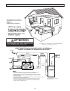
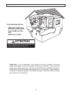
Locating the Exhaust Weatherhood
• At least 6' (2 m) from the ventilation air intake
• At least 18" (457 mm) above ground or above the
depth of expected snow accumulation
• At least 3' (1 m) away from the corner of the
building
• Not near a gas meter, electric meter or a walkway
where fog or ice could create a hazard
• Not into a garage, workshop or other unheated
space
When installing the weatherhood, its outside perimeter
must be sealed with exterior caulking.
Installing the ducting from the
weatherhoods to the HRV/ERV
The inner and outer liners of the flexible insulated duct
must be clamped to the sleeve of the weatherhoods
(as close to the outside as possible) and the appropri-
ate port on the HRV/ERV. It is very important that the
fresh air intake line be given special attention to make
sure it is well sealed. A good bead of high quality
caulking (preferably acoustical sealant) will seal the
inner flexible duct to both the HRV/ERV port and the
weatherhood prior to clamping.
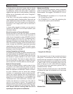
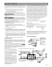
To minimize air flow restriction, the flexible insulated
duct that connects the two outside weatherhoods to
the HRV/ERV should be stretched tightly and be as
short as possible.
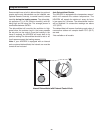
Twisting or folding the duct will severely restrict air
flow. See below for the recommended connection of
flexible insulated ducts to the the outside weather-
hoods and the HRV/ERV.
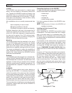
Warmside Ducting
To maximize airflow in the ductwork system, all ducts
should be kept short and have as few bends or elbows
as possible. Forty-five degree elbows are preferred to
90° elbows. Use “Y” tees instead of 90° elbows when-
ever possible.
All duct joints must be fastened with screws, rivets or
duct sealant and wrapped with a quality duct tape to
prevent leakage. We recommend aluminum foil duct
tape.Galvanized ducting from the HRV/ERV to the liv-
ing areas in the house is recommended whenever
possible, although flexible duct can be used in moder-
ation if necessary.To avoid possible noise transfer
through the ductwork system, a short length (approxi-
mately 12 " or 300 mm) of non-metallic flexible
insulated duct should be connected between the
HRV/ERV and the supply/ exhaust ductwork system.
The main supply and return lines to/from the
HRV/ERV must be 6 inches (150 mm) minimum.
Branch lines to the individual rooms may be as small
as 4 inches (100 mm), but 5 inch (125 mm) lines are
preferred .
All ducts running through attics and unheated spaces
must be sealed and insulated to code.
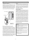
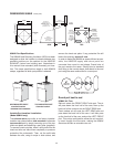
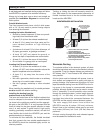
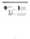
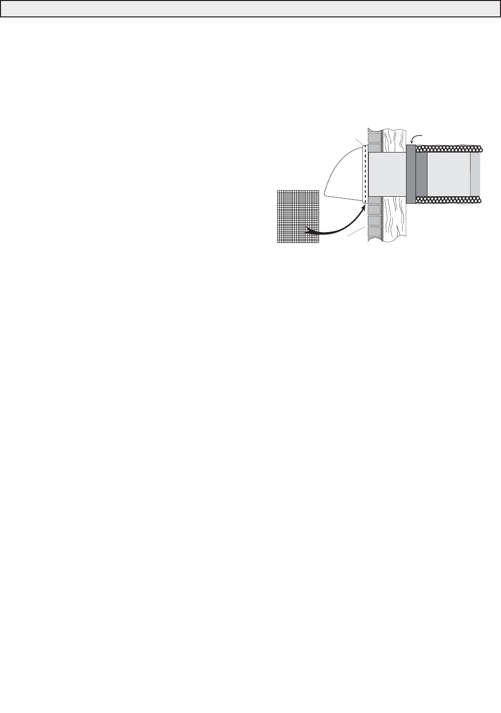
1. ThermalCollarslidesovergalvanized
sleeveofWeatherhood.
2. FastenThermalCollartoBelt.
3. SlidetheInsulatedFlexibleDuctingover
theWeatherhood'sgalvanizedsleeveand
fastenittotheThermalCollar.
4. Hoodishingedtoallowforeasyaccess
forcleaningofbirdscreen.
WEATHERHOODINSTALLATION
1/4"(6mm)SCREEN
(frontview)
EXTERIOR
WALL
SCREEN
(sideview)
COLLARISSUPPLIEDTO
ENSUREVAPOURBARRIER
IS100%SEALEDTO
WALLPLATE
12"galvanized
pipesupplied
Installing Air Ducts