


2
Introduction .........................................................................2
Warranty..............................................................................2
ERV Questions & Answers .................................................3
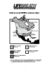
Climate Map........................................................................4
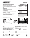
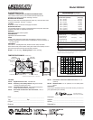
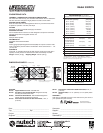
Technical Data - Model 95MAX ..........................................5
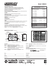
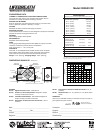
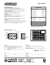
Technical Data - Model 155MAX ........................................6
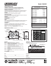
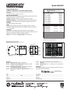
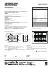
Technical Data - Model 155ECM ........................................7
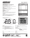
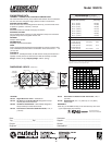
Technical Data - Model 155MAX RX ..................................8
Technical Data - Model 200MAX ........................................9
Technical Data - Model 200MAX RX ...............................10
Technical Data - Model MAXTOP.....................................11
Technical Data - Model 195DCS.......................................12
Technical Data - Model 300DCS.......................................13
Technical Data - Model 200ERV.......................................14
Technical Data - Model 200ERVD ....................................15
Function and Control.........................................................16
Glossary of Terms.............................................................16
Selecting Speeds and Modes of Operation.......................17
The Control Pad Mounted in the Control Module..............18
Optional Remote Controls.................................................19
Using the Dehumidistat.....................................................20
Schematic Diagram - Model 95MAX.................................21
Installation.........................................................................22
Installing Air Ducts ...........................................................23
Supply Air Ducting.............................................................24
Stale Air Exhaust System..................................................24
Dampers and Grilles .........................................................24
Installation Diagrams ..................................................25-28
Air Flow Balancing ...........................................................29
Maintenance Routine For HRV .........................................31
Maintenance Routine For ERV .........................................32
Troubleshooting ................................................................33
Interlocking HRV Operation to an Airhandler/
Furnace Blower.................................................................34
Wiring Diagrams ..........................................................35-36
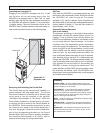
Before installation, careful consideration must be given to
how this system will operate if connected to any other piece
of mechanical equipment, i.e. a forced air furnace or air
handler, operating at a higher static. After installation, the
compatibility of the two pieces of equipment must be con-
firmed by measuring the airflow’s of the Heat Recovery
Ventilator (HRV) Energy Recovery Ventilator (ERV) by
using the balancing procedure found in this manual.
It is always important to assess how the operation of any
HRV/ERV may interact with vented combustion equipment
(ie. Gas Furnaces, Oil Furnaces, Wood Stoves, etc.).
NEVER install a ventilator in a situation where its normal
operation, lack of operation or partial failure may result in
the backdrafting or improper functioning of vented combus-
tion equipment!!!
HRV - Aluminum Core
A Heat Recovery Ventilator (HRV) is designed to provide
fresh air into a building while exhausting an equal amount
of stale air. During the winter months, the incoming cold
fresh air is warmed by utilizing the heat recovered from the
stale air before it is exhausted to the outdoors. During sum-
mer months when the indoor space is air conditioned, the
Heat Recovery Ventilator will help in cooling the incoming
fresh air with the stale air that is being exhausted.
ERV - Enthalpic Paper Core
An Energy Recovery Ventilator (ERV) is designed to pro-
vide fresh air into a building while exhausting an equal
amount of stale air. An ERV is designed for use in warm
humid areas with heavy air conditioning use. The ERV will
transfer both sensible and latent heat from the incoming
fresh air to the outgoing stale air thereby reducing the load
(due to ventilation) on the air conditioning system.
ERVs are not suitable for climates where the temperature
drops below -4°C (25°F).
All Heat Recovery Ventilators carry a Lifetime Warranty on
the heat recovery core and a 5 (five) year replacement
parts warranty.
All Energy Recovery Ventilators carry a 5 (five) year war-
ranty on the energy recovery core and a 5 (five) year
replacement parts warranty.
During the warranty period, if any core experiences a failure
or perforation caused by normal use while owned by the
original purchaser, a replacement core (FOB our plant) will
be supplied at no expense.
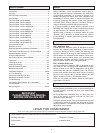
Table of Contents
Introduction
Caution
Warranty
LEAVE FOR HOMEOWNER
NOTE: Due to ongoing research and product development, specifications, ratings and dimensions are subject to change without notice.
TO BE COMPLETED BY CONTRACTOR AFTER INSTALLATION
Installing Contractor _________________________________________Telephone / Contact_____________________
Serial Number______________________________________________Installation Date ________________________
Model _________________________________________________________________________________________
IMPORTANT -
PLEASE READ THIS MANUAL
BEFORE INSTALLING UNIT.