


WATER SUPPLY AND PLUMBING
1. The fill valve is sized for an extended water
pressure range of 30 to 80 psi.
2. For cases below 15 psi add a pressure boost
pump, notify the factory and a fill valve with an
oversized orifice will be supplied.
3. For cases above 80 psi, install a pressure
reducing valve in the water feed line to the
unit.
4. With extremely dirty or muddy water sources,
e.g., some well sources, ensure proper
filtration by adding an external filter to the
water line entering the unit. (Consult factory
for accessories such as filters.)
5. DO NOT use completely demineralized water
with this unit as it is the minerals that allow the
electrode principle to work.
6. DO NOT use a hot water source as it will
cause deposits that will eventually block the fill
valve orifice.
.
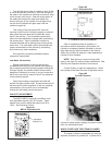
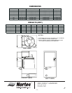
WATER CONNECTION
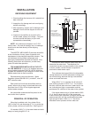
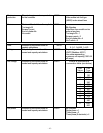
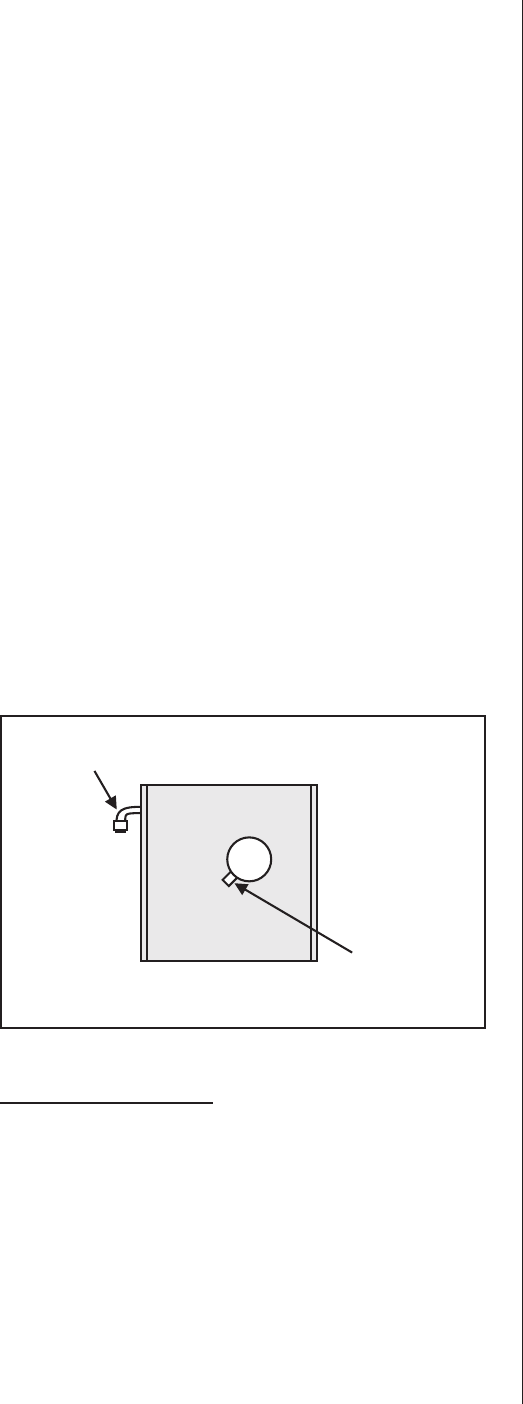
1. A copper compression olive type coupling for
1/4" O.D. soft copper tubing is provided with
unit and requires no soldering for the water
connection to the unit. See Figure #2.
2. An isolating valve should ALWAYS be placed
in the feed water line allowing service of the fill
valve.
3. Each unit is fitted with a fill solenoid valve
located on the base drain pan. Flow orifices
are designed for water pressure from 30 to 80
psi and are protected by the built-in strainer.
4. For inlet water pressure outside this range, the
factory should be contacted. (See Water
Supply and Plumbing section of this manual.)
START-UP AND OPERATION
· Ambient temperature location for humidifier:
41ºF - 104ºF (5ºC - 40ºC).
· Relative humidity location for humidifiers:
5% rh - 80% rh.
Check to see that the unit is securely mounted on
a level surface with the proper drain and water supply.
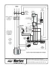
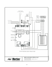
Check for correct voltage with appropriately sized
service. Check that the steam distributor, steam
supply hose, and condensate line are correctly
installed and routed back to the unit. Ensure that the
external control humidistat is located in an area to
properly sense the relative humidity to be maintained
by the humidifier, and that the interconnecting low
voltage wires between the humidistat and the unit’s
control terminal strip are in accordance with the wiring
diagram.
Check all electrical connections for wires which
may have become loose in shipping. Components
damaged due to loose connections are NOT under
warranty.
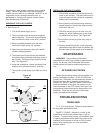
Check electrode plugs to ensure they are pressed
firmly onto the electrode pins. Important: Loose
connections will cause overheating of the cylinder
plugs, possibly melting the plugs and/or cylinder.
Open the isolating valve in the feed water line to
the unit.
Make sure the humidistat is set high enough to call
for humidification.
Turn on the main disconnect in the primary service
feeding the unit and check that unit has power at the
primary terminal block.
PUSH THE AUTO ON/OFF/DRAIN SWITCH TO
“ON”.
Water will start to enter the cylinder through its
bottom port and rise in the cylinder to a point
determined by the solid-state control circuitry.
It is not unusual upon initial start-up for the
water to fill the cylinder and cycle on the red high
water sensor light.
-2-
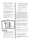
3/8" Cold Water
Olive Connection
7/8" Drain
Connection
Use 7/8" I.D. Hose From Factor
y
Figure #2
Bottom View of MES-U/MES-P Unit