


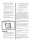
INSTALLATION
RECEIVING EQUIPMENT
1. Check packing slip to ensure ALL material has
been received.
2. Inspect box for damage and note on shipping
waybill accordingly.
3. After unpacking, inspect unit for damage and if
damage is found, advise shipper as soon as
possible.
4. Inspect unit (humidifier) to ensure it is the
correct model, phase, and voltage. If any are
incorrect, advise the factory or your local
representative immediately.
NOTE: All products are shipped on an F.O.B.
factory basis. Any and all damage, loss, or breakage
claims are to be made directly to the shipping
company.
The NORTEC MES-U/MES-P electrode humidifier
is the culmination of many years of research and
development in the electrode humidifier industry. This
unit has been built by skilled craftspeople and
thoroughly tested before shipment and should, if the
following instructions are observed, provide many
years of trouble-free operation.
FOR HUMIDIFIERS INSTALLED IN THE CITY
OF LOS ANGELES: A city of Los Angeles approved
spring-loaded double ball CHECK VALVE should be
supplied and installed by the contractor on each of the
potable water inlets to each humidifier.
Recommended valve manufacturer: Watts
Regulator (phone 508-688-1811), model #7, size 3/8”
NPT inlet and outlet.
Each drain line from these humidifiers shall be
routed, without dips or sags, to terminate above the
flood level rim of a City of Los Angeles approved
indirect waste receptor.
No combustible materials shall be placed in the
duct and/or the air plenum.
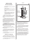
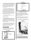
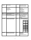
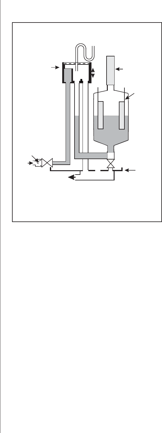
PRINCIPAL OF OPERATION
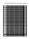
When the humidistat calls, the cylinder fills to
100% of the Full Load Amperage (F.L.A.) or to the top
of the cylinder, whichever comes first. See Figure #1.
If it reaches 100% F.L.A. the water heats and boils
away to a level giving 80% F.L.A.
An electronic timer uses the rate of amp fall to
determine the water level. The objective is to
concentrate current-carrying minerals in the cylinder
so that a smaller volume of water is required to
produce the rated steam output.
This achieves the longest life for the disposable
cylinder because of minimal electrode coverage and
use of less energy because the high concentration
allows a minimal drain rate.
When 80% F.L.A. is reached, the fill valve will
open refilling cylinder to 100% F.L.A. On occasion,
the drain valve will also come on if water level is too
low, indicating too high a concentration and the
requirement for a dilution of the water in the cylinder.
If the water reaches top of cylinder before 100%
F.L.A., the fill valve shuts off via the sensor and
fill-boil-fill-boil cycle continues, cycling off the red high
water sensor light until the concentration becomes
high enough to reach 100% F.L.A. The above
described control process will then take over.
-1-
Figure #1
O
p
e
r
-
a
-
ti
o
n
S
c
h
e
-
m
CONDENSATE RETURN
(OPTIONAL)
1” AIR
GAP
FILL
CUP
1. INLET CHAMBER
3. WATER OVERFLOW
CHAMBER (SAFETY DRAIN
IN CASE OF FILL VALVE/
CONTROL BOARD FAILURE)
STRAINER
FILL
VALVE
TAP
WATER
SUPPLY
DRAIN
CONNECTION
DRAIN
PAN
DRAIN CANAL
(OPEN TOATMOSPHERE)
DRAIN
VALVE
CYLINDER
1
2
3
2
. FILL CHAMBER
STEAM HOSE
ELECTRODE
S