


10-10
Page 19
2008-04-11
M. PILOT LINES
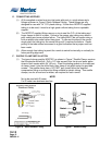
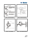
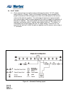
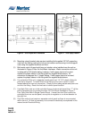
(1) All air pressure lines connecting to the control panel must be 1/4” O.D. plastic
tubing rated for 150 psig. Figure 16 Schematic Plumbing Layout illustrates the
proper connections of the air supply to and from the control panel to the vacuum
valve and the pilot air regulator. The control panel requires an input pneumatic
(air) control supply, which is usually tapped off the main air supply line upstream of
the pilot air regulator. The control panel has two pneumatic fittings located on its
top plate; one marked “pilot in” and the other marked “pilot out”. The “pilot in” is
connected to the control supply with the 1/4” plastic tubing. A second 1/4” line
connects the “pilot out” to both the pilot air regulator and the vacuum valve using a
“T” connector.
Figure 16. Schematic Plumbing Layout