


10-10
Page 17
2008-04-11
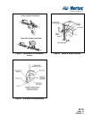
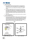
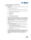
I. PRIMARY AIR PRESSURE CONTROL
(1) The primary air pressure control section (with the shutoff valve) is connected to the
air compressor or the compressed air source as specified in the Designer
produced drawings. See Figure 12 Primary Air Pressure Control Section.
J. PRIMARY WATER PRESSURE CONTROL
(1) The primary water pressure control section connects the main water supply. The
shutoff valve end of section is the inlet. The gauge end of the section is joined to
the water inlet of the vacuum valve for AFE systems. See Figure 13 Primary Water
Pressure Control Section.
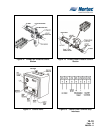
K. CONTROL PANEL
(1) Bolt the panel directly to the surface through the mounting holes. Place the panel
level against the surface and mark locations for holes to be drilled. Remove the
panel and drill 2 holes (hole size to match field supplied lag bolts and anchors).
Place panel over the holes and secure it using bolts.
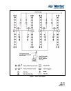
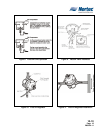
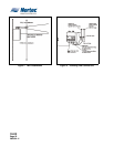
L. ELECTRICAL WIRING
(1) Electrical connections of the control panel use 18 ga wire for all external wiring.
The control panel requires 24 VAC, which is provided by the NORTEC supplied
step down transformer (120 VAC to 24 VAC). The transformer plugs into any
standard 120 VAC outlet that must be located within 6’ (six feet) of the control
panel. Power is connected to the low voltage terminal trip located inside the panel
as illustrated in Figure 16 Control Panel Terminal Strip Interfaces. Control panels
are supplied by NORTEC in two configurations. The first is for use with systems
that are designed to operate with only an On/Off humidistat and the second is
designed to operate with a modulation controller. Within the control panel there is
a 7 point terminal block, terminals 6 & 7 are for power voltage 24 VAC. A wiring
diagram is provided with each control panel. Both control panels reserve terminals
1 & 2 are for on/ off control wiring which may be a simple humidistat, a relay for
remote operation or other interlock devices (dry make break contacts).
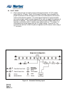
(2) Modulation controlled systems use terminal 3, 4 & 5 on the 7 terminal block strip as
follows: terminal 3 is to be connected to the “+” terminal on the controller, terminal
4 is to be connected to the “-“ terminal on the controller and terminal 5 is for 24
VAC supply to the controller. This is illustrated in Figure 15 Control Panel Terminal
Strip Interfaces.