


8
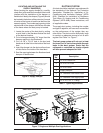
Connecting the Return and Supply Air
Flexible Ducts
• The return duct for all units is 14” diameter.
• The supply duct for all units is 12” diameter.
• The fl exible ducts can be connected to the
corresponding fi ttings with the clamps provided
with the ducts. Note: To prevent a loss in
cooling capacity, make sure all connections
are tight.
• The fl exible ducts may be cut to the required
length, see instructions packed with duct. Keep
all ducts as short and straight as possible.
Avoid sharp bends.
• Ducts may be spliced with sheet metal sleeves
and clamps.
• Once the inner duct is connected to the proper
fi tting, the insulation and plastic sleeve should
be pulled over the connection and clamped.
• Homes with multiple supply ducts (or special
applications), a Y fi tting is available to divide
the supply air so it can be ducted to different
areas of the home for more effi cient cooling.
Note: For maximum performance, insulate
the Y fi tting.
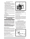
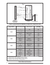
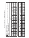
Blower Speed
For optimum system performance and comfort,
it may be necessary to change the factory speed
setting. See Table 2 (page 10) for factory settings.
NOTE: Q5RE models have High Effi ciency Motors
with 5 speed taps.
WARNING:
To avoid electric shock, personal
injury, or death, turn off the electric
power at the disconnect or the main
service panel before making any
electrical connections.
1. Disconnect all electrical power to the unit and
remove the service panel.
CAUTION:
Label all wires prior to disconnection
when servicing controls. Wiring
errors can cause improper and
dangerous operation. Verify proper
operation after servicing.
2. Locate the orange, black and red wires
terminated to the blower motor. The orange
wire controls the low speed cooling and heating
operations, the black wire controls high speed
cooling and heating operations and the red
wire controls the electric heating operation.
CAUTION:
To avoid personal injury or
property damage, make certain
that the motor leads cannot
come into contact with any metal
components of the unit.
3. Verify the required speed from the airfl ow data
found in Table 2. Place appropriate wire on the
appropriate motor speed tap for the required
airfl ow.
4. Check all factory wiring per the unit wiring
diagram and inspect the factory wiring
connections to be sure none loosened during
shipping or installation.
ELECTRICAL CONNECTIONS
WARNING:
To avoid electric shock, personal
injury, or death, turn off the electric
power at the disconnect or the
main service panel before making
any electrical connections.
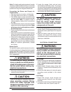
High Voltage
1. Install a branch circuit disconnect of adequate
size as specifi ed by the National Electrical
Code. Locate the disconnect within sight
of the unit.
2. Extend leads through power wiring hole
(Figure 9). Connect L1 and L2 directly to the
contactor.
3. Ground the heat pump unit using the green
grounding screw provided in the control
panel.
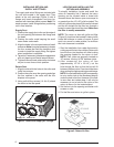
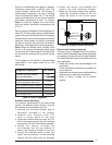
Low Voltage
1. Route 24V control wires through the
sealing grommet (Figure 8) near the power
entrance.
2. Connect the control wires to the defrost board
and blower relay wire (Figure 9, page 10).
Note: For highly resistive duct systems it may be
necessary to add an additional return air duct and
or supply to achieve maximum performance and
prevent coil icing and refrigerant fl ood back.