


7
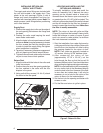
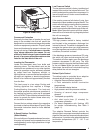
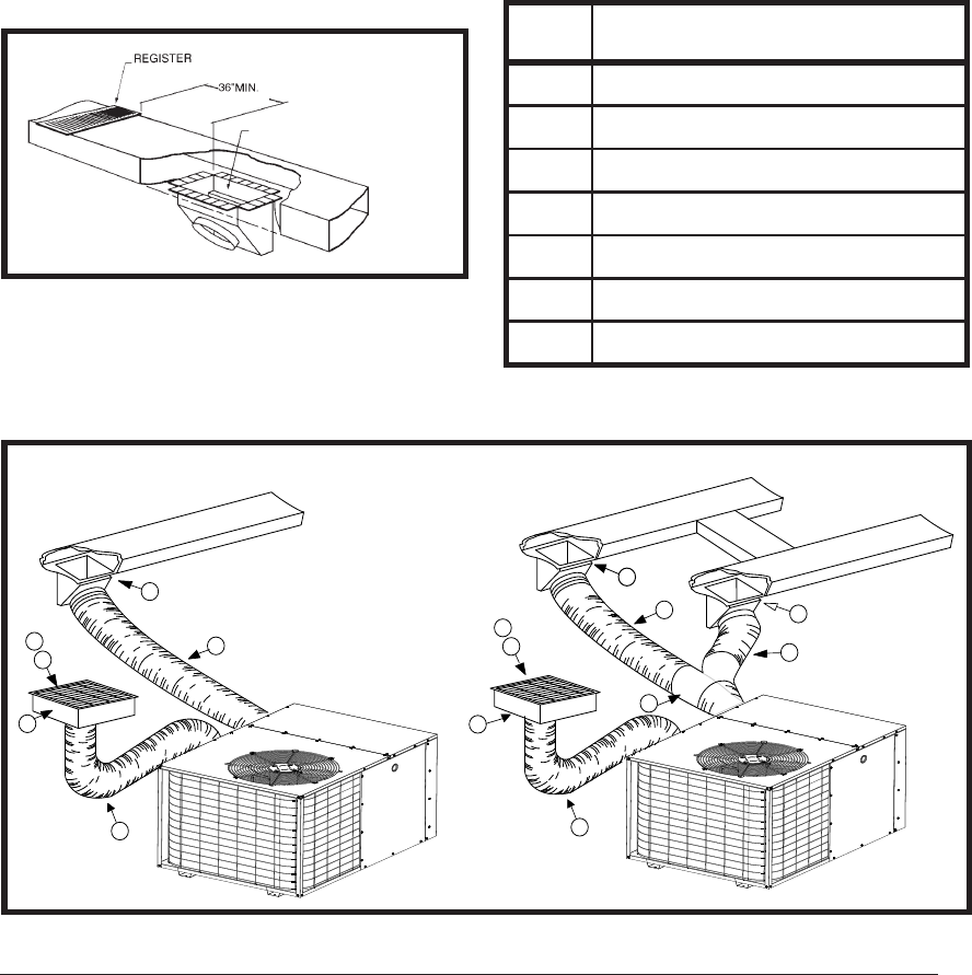
Figure 6. Supply Damper
AUTOMATIC DAMPER IS CLOSED
WHEN HEAT PUMP IS OFF
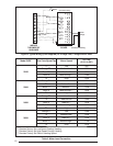
Item
No.
Description
1
12” x 20” Return Air
2
16” x 20” Air Filter
3
12” x 20” Grille
4
Supply Damper
5
14” Diameter Flex Return Duct
6
12” Diameter Flex Supply Duct
7
12” x 12” x 12” “Y” Fitting
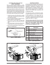
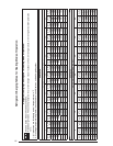
Table 1. Typical Applications
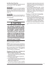
LOCATING AND INSTALLING THE
SUPPLY DAMPER(S)
When locating the supply damper(s), carefully
check fl oor joists and frame members that could
interfere with the installation of the damper or
fl exible duct. Ideally, the damper (Figure 6) should
be located in the bottom of the main duct, forward
of center of the home, at least three feet from the
nearest register. The round supply opening in the
slanted side of the damper should face the side
of the home where the heat pump is located.
1. Locate the center of the heat duct by cutting
a small hole in the fi berboard below the duct
at the desired location.
2. Cut a hole approximately 3/4” larger than the
damper opening in the fi berboard.
3. Cut a 9-1/8” x 13-1/8” hole in the duct and
bend over all tabs fl at on the inside of the heat
duct.
4. Insert the damper into the duct and bend over
all tabs fl at on the inside of the heat duct.
5. Seal the opening between the fi berboard and
damper or fl exible duct.
DUCTING SYSTEM
Air ducts should be installed in accordance with
the standards of the National Fire Protection
Association “Standard for Installation of Air
Conditioning and Ventilation Systems” (NFPA
90A), “Standard for Installation of Residence
Type Warm Air Heating and Air Conditioning
Systems” (NFPA 90B), these instructions, and
all applicable codes.
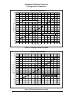
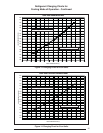
The supply duct system, including the number
and type of registers, will have much more effect
on the performance of the system than any
other factor. The duct must be suffi ciently large
to conduct an adequate amount of air to each
register. See Table 1 or Figure 7.
The heat pump system will not cool or heat
the home if air is lost to the outside through
leaks in the duct system. Ducts that are
collapsed or restricted by foreign objects
will also prevent adequate air fl ow.
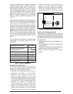
MULTIPLE DUCT APPLICATIONSINGLE DUCT APPLICATION
6
6
4
4
5
2
3
1
5
2
3
6
4
1
7
Figure 7. Single and Multiple Duct Applications