33
• Change or replace the air filters monthly
during any period when the circulating
blower is operating regularly.
• Always replace the doors on the furnace
after servicing. Do not operate the furnace
without all doors and covers in place.
• Avoid operating the furnace when win-
dows and doors are open.
• Be sure that the thermostat is properly
installed and is not being affected by drafts
or heat from lamps or other appliances.
Sequence of Operation
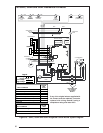
Operating sequences for the heating, cooling,
and fan modes are described below. Refer to the
wiring diagrams (Figures 26 and 27) and the low
voltage field wiring diagram (Figure 24).
Heating Mode:
1. On a call for heat the thermostat closes,
applying 24 VAC to the W terminal on the
control board.
2. The control board checks for continuity on
the 24 VAC limit control circuit (over-tem-
perature limit switch, flame rollout switches
and blocked vent switch in series). If an
open limit is detected the control board will
energize the inducer and the conditioned
air blower. All other system functions will be
inoperable until the limit circuit closes. While
the limit is open, the red LED will pulse at
a rate of 1 blink per unit time.
3. The furnace control checks for continuity
across the pressure switch (24 VAC). If the
pressure switch is closed the heat mode
sequence will not continue. If it remains
closed for 10 seconds the red LED will blink
3 times repetitively until the fault condition
clears.
4. The inducer is energized.
5. The pressure switch will close. If the pres-
sure switch does not close after 10 seconds
the fault LED will blink 2 times repetitively
and the inducer will continue to run until the
switch is closed.
6. The inducer will pre-purge for 30 seconds
and then the ignitor will start its warm-up.
After 30 seconds of ignitor warm-up the gas
valve (24 VAC) will open. The ignitor circuit
stays energized for 6 seconds after the gas
valve opens.
7. The furnace control must prove flame via
the flame sensor six seconds after the gas
valve opens. If flame is sensed, all burners
are on and the ignitor cools off. If no flame
is sensed, the gas valve closes immediately
and the inducer continues to run. A second
trial for ignition (step 6) begins if no flame is
sensed. On the fifth try for ignition, the
furnace control is locked out and the red
LED will blink 4 times repetitively. The ther-
mostat must be opened for at least ten
seconds to reset the furnace control after a
lock out. Otherwise, the furnace will attempt
another ignition sequence in 1 hour.
8. The furnace control energizes the circulat-
ing air blower on the heating speed 30
seconds after the gas valve circuit is ener-
gized .
9. When the thermostat has been satisfied,
gas valve is de-energized.
10. The inducer is de-energized after a 30
second postpurge.
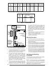
11. The furnace control keeps the circulating air
blower energized for 120 seconds (factory
set) or 60, 90, or 180 seconds (field adjust-
able). (See Figure 25.)
12. Abnormal conditions: If a limit opens during
operation, the inducer and circulating air
blower continue to operate. The gas valve is
de-energized immediately. The blowers
continue to operate until the limit closes.
When the limit closes the inducer blower is
de-energized immediately. The circulating
air blower continues to operate for the speci-
fied delay (factory set at 120 seconds).
Cooling Mode:
1. On a call for cooling the thermostat closes,
applying 24 VAC to the G and Y terminals
on the furnace control. This closes the
compressor contactor.
2. The furnace control energizes the circulat-
ing blower (115 VAC) on the cooling speed.
3. When the thermostat is satisfied, the G
and Y terminals on the control board are
de-energized opening the compressor con-
tactor.
4. The circulating air blower is de-energized
after a 90 second delay.


