


8
§4.0 INSTALLATION
PLEASE READ CAREFULLY BEFORE BEGINNING INSTALLATION. FAILURE TO FOLLOW
THESE PROCEDURES CAN RESULT IN DAMAGE TO YOUR SYSTEM AND VOID YOUR
WARRANTY.
§4.1 LOCATION
It is recommended that systems be located where they are protected from harsh environments
such as rain, snow and extreme temperatures (both hot and cold). MN-800 TF units can be
located just about anywhere there is a water and electrical supply. This can be on the floor,
mounted on the wall with a shelf, or any other flat surface. Keep in mind, however, that they
should be out of normal traffic patterns and should be easily accessed for daily monitoring and
service.
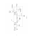
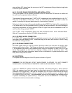
§4.2 SYSTEM PLUMBING INSTALLATION GUIDE LINES
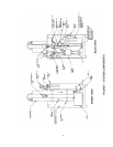
A complete plumbing diagram of the system installation is shown in Figure 2. Always abide by
local plumbing codes when installing the system. We recommend that a licensed plumbing
contractor install this system. When installation procedures conflict with your local plumbing
codes, STOP and contact Nimbus. This installation guide assumes the appropriate electrical
outlet, 2 city water valves (1/2” FPT) and 1 valve (1/2” FPT) for distribution to the food service
machines have been installed convenient to the system installation location. All threaded fittings
are to be installed with Teflon tape.
IMPORTANT:
FOR PLASTIC TUBING, USE ONLY SUPPLIED NYLON FERRULES AND
BRASS TUBE INSERTS. DO NOT USE BRASS FERRULES ON PLASTIC TUBING.
§4.2.1 TANK PREPARATION AND INSTALLATION
:
Install the 1-¼” x ¾” bushing In the 1-¼” FPT fitting at the bottom of the tank then install the ¾”
MPT x 5/8” compression elbow in the bushing. Direct the 5/8” compression end toward the
opening in the tank skirt. Cut a piece of black 5/8” tubing to extend about 4” beyond the tank
skirt. Then install the tubing into the 5/8” compression fitting on the tank outlet.
Follow the instructions included with the tank wall brace kit to secure the tank to the rear wall.
Locate the restraint brackets about 15” and 30” above the floor. Set the tank in place and
rotate it so the bottom tank outlet is positioned as desired. Tighten the bracket clamps securely
around the tank.
Remove the blue protective cap from the nut on top of the tank. Install the 5/8” x 1-½” long stud
in the nut. Install the black plastic feet on the legs of the RO frame then lift and place the RO
system on top of the tank with the threaded stud extending through the hole in the center of the
RO frame base. Install the flat washer and nut on the stud. Rotate the RO so there is access
to the 20” filters on the front of the unit. Tighten the 5/8” nut to secure the RO to the tank.
Install the ½” ball valve on the 5/8” tubing on the outlet of the tank. Use one straight and one
elbow of ½” MPT x 5/8” compression fitting. With these fittings the valve can be installed
straight out from the tank or pointing vertically up the side of the tank as desired. Connect a