


22
§9.2 TDS MONITOR INSTRUCTIONS
Model TDS-2B TDS Monitor
Part # 100860
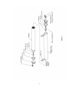
The Nimbus TDS-2B TDS Monitor is designed to operate within the Remote Bypass Unit of the
Nimbus MN system. It is installed inside the upper left corner of the Bypass Unit frame and is
connected to a tee fitting installed in the product water output line. The Monitor is powered by a
9V battery accessible via a sliding cover at the rear of the case. When the red front panel push-
button switch is pressed, the probe mounted in the product water line senses the TDS level in the
water flow. The monitor will then act to illuminate the green LED indicator if the product water
TDS is below the preset level or the red LED if the product water TDS exceeds the preset level.
The monitor is turned off when the push-button is released.
Specifications
Preset Level Selection* 50/75/100/150/200/250/300/500 ppm
(default 100 ppm)
Power Supply 9V DC
Sensing Method AC signal conductivity
Actuation Push-button switch
*Not temp compensated – levels calibrated to 25°C/77°F
Preset Level Adjustment
The TDS Monitor is preset to 100 ppm. To change the preset level, remove the small screw at
the center of the rear cover. Carefully remove the rear cover assembly. On the circuit board
inside the rear cover locate the 8-position selector switch. The switches marked 1 through 8
determine the preset level. With a ballpoint pen or small screwdriver place the number 3 switch in
the “OFF” position, then place the new TDS level switch in the “ON” position (top end depressed).
The corresponding TDS preset for each switch is as follows 1=50, 2=75, 3=100, 4=150, 5=200,
6=250, 7=300, 8=500. Only one of the eight switches should be in the “ON” position. When
finished, re-install the assembly in reverse order.