


contents vii
FIGURES
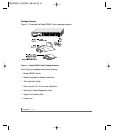
Figure 1-1. Model GS524T Switch Package Contents 1-2
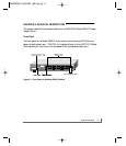
Figure 2-1. Front Panel of the Model GS524T Switch 2-1
Figure 2-2. Rear Panel of the Model GS524T Switch 2-2
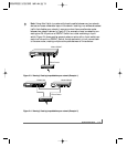
Figure 2-3. Warning! Creating loops disables your network
(Example 1) 2-3
Figure 2-4. Warning! Creating loops disables your network
(Example 2) 2-3
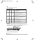
Figure 2-5 Rear Panel of the Model GS524T Switch 2-4
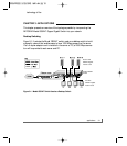
Figure 3-1. Model GS524T Switch Used as a Desktop Switch 3-1
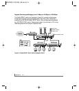
Figure 3-2. Model GS524T Switch Used as a Segment Switch 3-2
Figure 4-1. Attaching Mounting Brackets 4-2
Figure 4-2. Connecting to the Model GS524T Switch 4-3
Figure B-1. RJ-45 Plug and RJ-45 Connector
with Built-in LEDs B-1
Figure C-1. Straight-through Twisted Pair Cable C-5
Figure C-2. Crossover Twisted Pair Cable C-5
Figure C-3. Category 5e UTP Patch Cable with
Male RJ-45 Plug at Each End C-6