


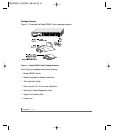

physical description 2-4
100-240 VAC 50-60 Hz
AC power Receptacle
Fans
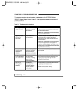
LEDs
Table 2-1 describes the activity of the LEDs.
Table 2-1. LED Descriptions
Label Color Activity Description
Power Green On Power is supplied to the switch.
Off Power is disconnected.
FDX/COL Green On The port is operating in full-duplex mode.
Off The port is operating in half-duplex mode.
Yellow Blinking Data collisions are occurring on the port. In a full-duplex
environment, there is no collision. In a half-duplex environment,
some collisions are normal.
Activity/ Green Blinking Packet transmission or reception is occurring on the port.
10M On A valid 10 Mbps link is established on the port.
Off No Activity on the port.
1000M Green On A valid 1000 Mbps link is established on the port.
Off A link is not established on the port.
100M Green On A valid 100 Mbps link is established on the port.
Off A link is not established on the port.
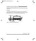
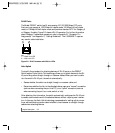
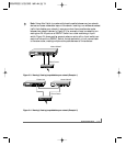
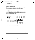
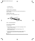
Rear Panel
As illustrated in Figure 2-5, the rear panel of the Model GS524T switch has fans for cool-
ing and a standard AC Power Receptacle for the supplied power cord.
Figure 2-5. Rear Panel of the Model GS524T Switch