


15
W415-0319 / D / 08.03.05
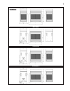
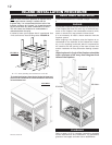
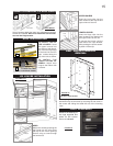
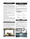
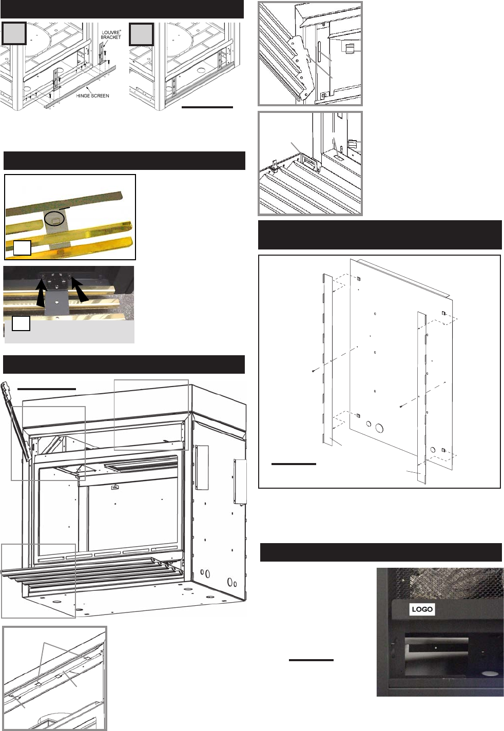
L36 LOUVRE INSTALLATION
FIGURE 32 a-c
HOOD
Attach the hood by pressing the
top flange into the clips along
the top of the louvre opening.
Secure using a screw through
the centre slot.
LOWER LOUVRES
Insert the hinge clips into the
slots located at the bottom left
and right corners of the unit.
To remove the louvres, pull the
back tabs of the clips forward,
while pushing the louvre assem-
bly back. Lift the clip.
UPPER LOUVRES
Insert the louvre tabs into the
slots located at the top left and
right corners of the unit.
SLOT
TAB
B
C
HINGE
CLIP
SLOT
A
B
C
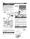
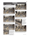
Remove the backing of
the logo supplied and
place on the screen
cover, as indicated.
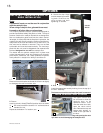
LOGO PLACEMENT
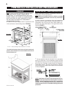
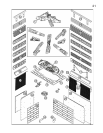
Using 6 screws, attach the lower louvre brackets and hinge
screen as illustrated. Be sure to install the louvre brack-
ets over the hinge screen.
A
B
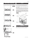
TO INSTALL THE UP-
PER LOUVRES: Insert
the upper louvres into
the slots on both brack-
ets. Press the top flange
of the hood into the four
clips located along the
top of the unit as shown.
TO INSTALL THE
LOWER LOUVRE AS-
SEMBLY: Attach each
hinge to the firebox with
2 screws.
FIGURES 29
LOWER LOUVRE BRACKETS & HINGE SCREEN
GVFL INSTALLATION
A
CLIPS
CENTRE
SLOT
FLANGE
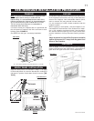
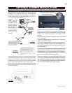
When using a non-combustible finishing material, the
stand-offs may be removed, by removing the set screw in
the centre and sliding the stand-offs out of the mounting
clips.
HEAT SHIELD STAND-OFF
REMOVAL
HEAT SHIELD
STAND-OFFS
END HEAT SHIELD SHOWN
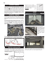
FIGURE 33
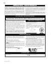
FIGURE 34
LOUVRE
HOOD
SLOT
BRACKET
30
LOWER LOUVRES
(VALVE CONTROL DOOR)
31