


10
W415-0619 / A /08.09.07
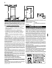
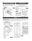
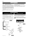
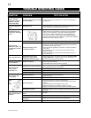
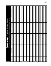
FRAME INSTALLATION
1. Align the two holes
in the upper portion
of the hinge on the
control door assembly
to those in the bottom
trim bracket and
secure using two of
the screws supplied.
(FIGURE 17)
2. Rest the top lip of the Torch
TM
frame on the top trim bracket,
and the securing tabs at the bottom of the Torch
TM
frame on
the bottom trim bracket.
3. Align the two slots in the top of the Torch
TM
frame with the
two holes in the top trim bracket and secure using two of the
screws supplied however do not fully tighten to leave room
for adjustment.
(FIGURE 18)
4. Align the holes in the securing tabs at the bottom of the
Torch
TM
frame with the holes in the bottom trim bracket and
secure using the two remaining screws, however do not fully
tighten to leave room for adjustment.
(FIGURE 20)
FIGURE 17
FIGURE 19
FIGURE 18
FIGURE 20
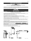
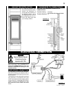
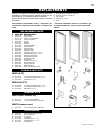
Before the glass door can be removed, the optional front
must be removed.
The glass door is secured to the top front edge of the fi rebox.
Pull the handles of the latches forward, then lift the hooks out
from the slots in the door frame to release the top of the door.
Then, pivot forward until the top edge of the door clears the
front of the fi replace. Next gripping the sides of the door lift
the door out from the retainer along the bottom of the door.
DOOR REMOVAL
FINISHING
FIGURE 16
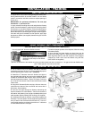
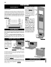
GLASS REMOVAL
Having removed the door, lay on a smooth fl at surface, face
down. There are 4 glass retainers that need to be bent away
from the glass to release it from the frame. Do not pry on
the glass.
When replacing DO NOT SUBSTITUTE MATERIAL, replace
the gasket (W562-0008) and the glass (W300-0088). Set
new glass into the frame and gently bend tabs into the
gasket to secure.
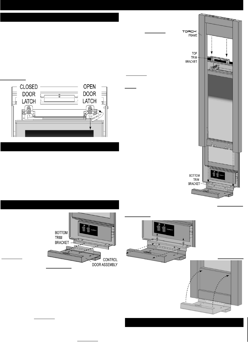
5. If required, the bottom
trim bracket can be adjusted
by loosening it’s securing
screws.
(FIGURE 19) Once
the Torch
TM
frame is perfectly
square and the control door
assembly will close without
rubbing against the sides of
the Torch
TM
frame, tighten all
screws and close the control
door assembly.
(FIGURE 20)
Note: The Torch
TM
frame
has been designed to
accommodate fi nished
material thicknesses of
1/2” - 3/4”. If it is necessary
to pull the Torch
TM
frame
out to the max. 3/4” the
magnetic catch will need
to be adjusted. Minor
adjustment can be made
by removing shims from
behind the magnet. Major
adjustments can be made
by moving the magnet to
the outside of the panel.
LIGHT INSTALLATION
Refer to the instructions included with the LK8 light kit when
installing lights into the frame.