17
W415-0153 / A / 10.29.01
REPLACEMENT BLOWER
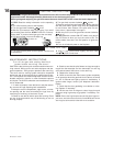
Blower replacement may be done through either the
firebox or from the rear of the unit. Using the rear panel
is recommended.
1. Turn off the electrical power and the gas supply to the
stove.
INSTALLATION THROUGH THE REAR
PANEL:
FOR MODEL GDS28
2. Remove the two combustion air covers and gaskets
held on with 4 screws each. Remove the rear panel held
in place with 6 screws.
3. Remove the 2 screws holding the blower to its mount-
ing plate. Disconnect the two blower wires.
4. Replace the blower and reconnect the two wires. When
replacing the rear panel, ensure that the wires are neither
pinched nor interfere with the blower operation. Ensure
that the combustion air cover plates and gaskets are prop-
erly installed and sealed.
FOR MODEL GS28
2. Remove the 8 screws securing the air intake manifolds
to the rear panel. Remove the rear panel held in place with
6 screws.
3. Remove the 2 screws holding the blower to its mount-
ing plate. Disconnect the two blower wires.
4. Replace the blower and reconnect the two wires. When
replacing the rear panel, ensure that the wires are neither
pinched nor interfere with the blower operation. Re-se-
cure the air intake manifolds.
INSTALLATION THROUGH THE FIRE-
BOX:
Replacement blower access gasket is required.
2. Open the lower control door, the two side doors, and the
fire viewing door. Remove the logs.
3. Remove the blower access plate held on with 6 screws.
4. Disconnect the two blower wires. Remove the blower
bracket held on with 2 screws.
5. Replace the blower using the existing bracket. Replace
the bracket/blower assembly on the unit.
6. Reconnect the two wires. Hold the replacement gasket
in place and reattach the blower access plate. Replace the
logs. Close all doors.
Turn the gas supply and electricity back on.
Because the blower is thermally activated, when turned
on, it will automatically start approximately 15-30 min-
utes after lighting the stove and will run for approximately
30-45 minutes after the stove has been turned off. Use
of the fan increases the output of heat.
Drywall dust will penetrate into the blower bearings caus-
ing irreparable damage and must be prevented from
coming into contact with the blower or its compartment.
Any damage resulting from this condition is not cov-
ered by the warranty policy.
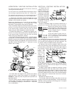
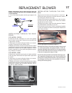
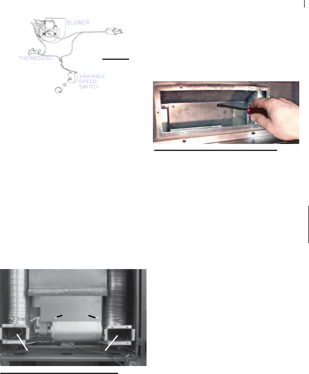
FIGURE 33
FIGURE 35 - INSTALLATION FROM THE FRONT
FIGURE 34 - INSTALLATION FROM THE REAR
BLOWER
SCREWS
AIR INTAKE MANIFOLDS


