


23
W415-0547 / C / 07.25.06
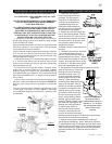
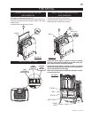
NOTE: Check and adjust, if necessary, the primary air
to
7
/
16
” for propane and
1
/
4
” for natural gas. Replace the
screws.
7. Turn on the gas supply and check for gas leaks by brushing
on a soap and water solution.
Do not use open fl ame.
8. Replace the log set. Then light the pilot and main burner
to ensure that the gas lines have been purged.
9. Replace the glass viewing door and cast front. Turn on
the electrical supply to the fi replace.
Purge all gas lines with the glass door removed.
Assure that a continuous fl ow is at the burner before
re-installing the door.
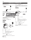
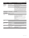
1. Turn off the electrical
and gas supply to the fi re-
place.
2. Remove the cast front,
glass viewing door and
log set.
3. Remove the 2 securing
screws. Slide the burner
assembly to the right and
lift out.
4. Using a deep
9
/
16
” socket
wrench, remove the main
burner orifi ce. A
7
/
8
” back-up
wrench must be used on
the manifold, located below
the housing to ensure that
the aluminum tubing does
not twist or kink. Replace
the correct burner orifice
using pipe thread compound.
5. Loosen nut and replace with appro-
priate injector
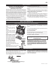
6. Reinstall the burner ensuring that the
Venturi tube fi ts over the orifi ce.
ORIFICE
LOCATION
BURNER
ASSEMBLY
FIGURE 37
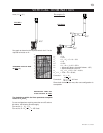
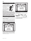
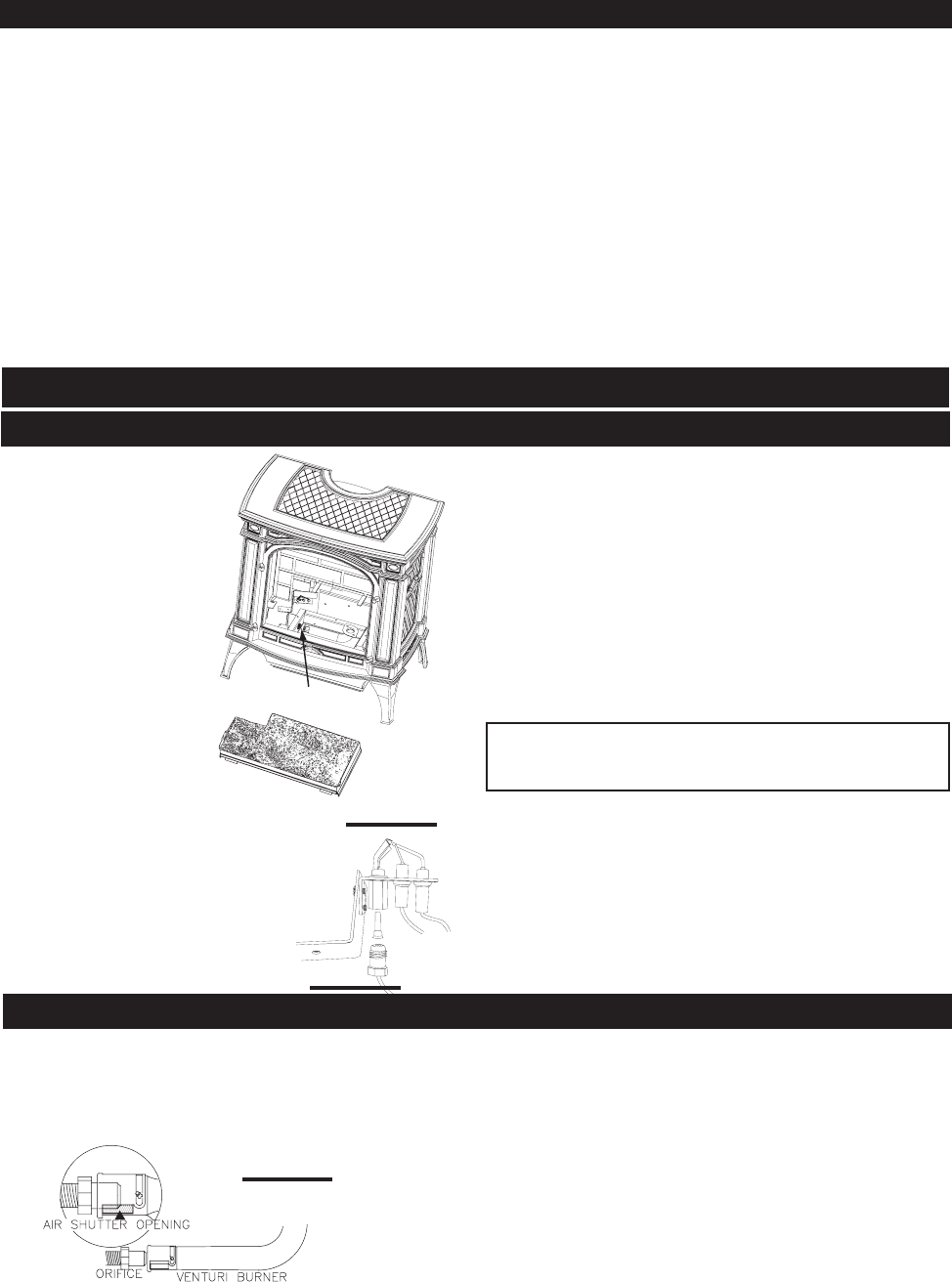
Air shutter adjustment must only be done by a
qualifi ed gas installer!
FIGURE 36
ADJUSTMENTS
PILOT INJECTOR AND ORIFICE REPLACEMENT
VENTURI ADJUSTMENT
TURN OFF THE GAS AND UNPLUG
ELECTRICAL POWER BEFORE
SERVICING THE STOVE!
CAUTION: Label all wires prior to disconnection when servic-
ing controls. Wiring errors can cause improper and dangerous
operation. Verify proper operation after servicing. This stove
and its venting system should be inspected before use and
at least annually by a qualifi ed service person. The fi replace
area must be kept clear and free of combustible materials,
gasoline or other fl ammable vapours and liquids. The fl ow of
combustion and ventilation air must not be obstructed.
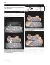
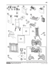
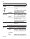
1. In order to properly clean the burner and pilot assembly,
remove the logs exposing both assemblies.
2. Keep the control compartment, logs, burner, air shutter
opening and the area surrounding the logs clean by vacuum-
ing or brushing, at least once a year.
3. Check to see that all burner ports are burning. Clean out
any of the ports which may not be burning or are not burning
properly.
4. Check to see that the pilot fl ames are large enough to
engulf the thermocouple and the thermopile on one leg and
reaches toward the burner on the other leg.
5. Replace the cleaned logs.
6. Check to see that the main burner ignites completely on
all openings when the gas knob for the burner is turned on.
A 5-10 second total light-up period is satisfactory. If ignition
takes longer, consult your Napoleon dealer/distributor.
7. Check that the door gasketing is not broken or missing.
MAINTENANCE
Remove the 2 screws securing the burner. Natural gas models
have air shutters set to 0.25" open (1/4"). Propane models
have air shutters set to 0.438" open (7/16").
After making adjustments replace the burner ensuring that the
venturi tube fi ts over the orifi ce and replace the screws.
Closing the air shutter will cause a more yellow fl ame, but
can lead to carboning. The fl ame may not appear yellow
immediately; allow 15 to 30 minutes for the fi nal fl ame
colour to be established.
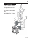
FIGURE 35
This must be carried out by an AUTHORIZED
REPRESENTATIVE OF WOLF STEEL LTD. or a QUALIFIED
GAS INSTALLER in accordance with local codes or in the
absence of local codes with the requirements of the provin-
cial / state authorities having jurisdiction and in accordance
with the requirements of the CAN1-B149 Installation Code in
Canada and the ANSI Z223.1 National Fuel Gas Code in the
United States.