


17
W415-0547 / C / 07.25.06
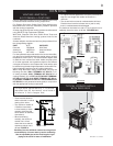
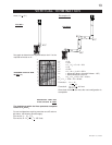
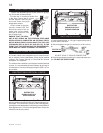
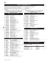
1. Fasten the roof support
to the roof using the screws
provided. The roof support
is optional. In this case the
venting is to be adequately
supported using either an
alternate method suitable to
the authority having jurisdiction
or the optional roof support.
2. Stretch the inner aluminum fl ex
liner to the required length. Slip the
liner a minimum of 2” over the inner
sleeve of the air terminal connector
and secure with 3 #8 screws. Seal
using a heavy bead of the high
temperature sealant.
3.Repeat using the outer aluminum
fl ex liner.
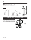
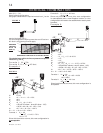
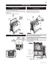
4. Thread the air terminal connector
/ liner assembly down through
the roof. The air terminal must be
located vertically and plumb. Attach
the air terminal connector to the roof
support, ensuring that the top of the
air terminal is 16” above the highest
point that it penetrates the roof.
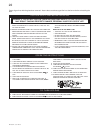
5. Remove nails from the shingles, above and to the
sides of the chimney. Place the
fl ashing over the air terminal
connector leaving a min. 3/4”
of the air terminal connector
showing above the top of the
fl ashing. Slide the fl ashing
underneath the sides and upper
edge of the shingles. Ensure
that the air terminal connector
is properly centred within the
fl ashing, giving a 3/4” margin
all around. Fasten to the roof.
Do not nail through the lower
portion of the fl ashing. Make
weather-tight by sealing with
caulking. Where possible, cover
the sides and top edges of the
fl ashing with roofi ng material.
6. Aligning the seams of
the terminal and air terminal
connector, place the terminal
over the air terminal connector
making sure the liner goes into the hole in the terminal.
Secure with the three screws provided.
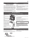
7. Apply a heavy bead of weatherproof caulking 2
inches above the fl ashing. Note: Maintain a minimum
2” space between the air inlet base and the storm collar.
Install the storm collar around the air terminal and slide
down to the caulking. Tighten to ensure that a weather-
tight seal between the air terminal and the collar is
achieved.
VERTICAL VENTING INSTALLATION
FOLLOW THE VENTING INSTRUCTIONS EXACTLY.
ALL HORIZONTAL VENT RUNS MAY HAVE A 0" RISE
PER FOOT.
FOR OPTIMUM PERFORMANCE IT IS RECOMMENDED
THAT ALL HORIZONTAL RUNS HAVE A MINIMUM
¼ INCH RISE PER FOOT.
ALL INNER EXHAUST AND OUTER INTAKE VENT PIPE
JOINTS MAY BE SEALED USING EITHER RED RTV
HIGH TEMP SILICONE SEALANT OR BLACK HIGH
TEMP MILL PAC WITH THE EXCEPTION OF THE FIRE-
PLACE EXHAUST FLUE COLLAR WHICH MUST BE
SEALED USING MILL PAC (NOT SUPPLIED).
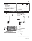
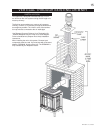
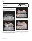
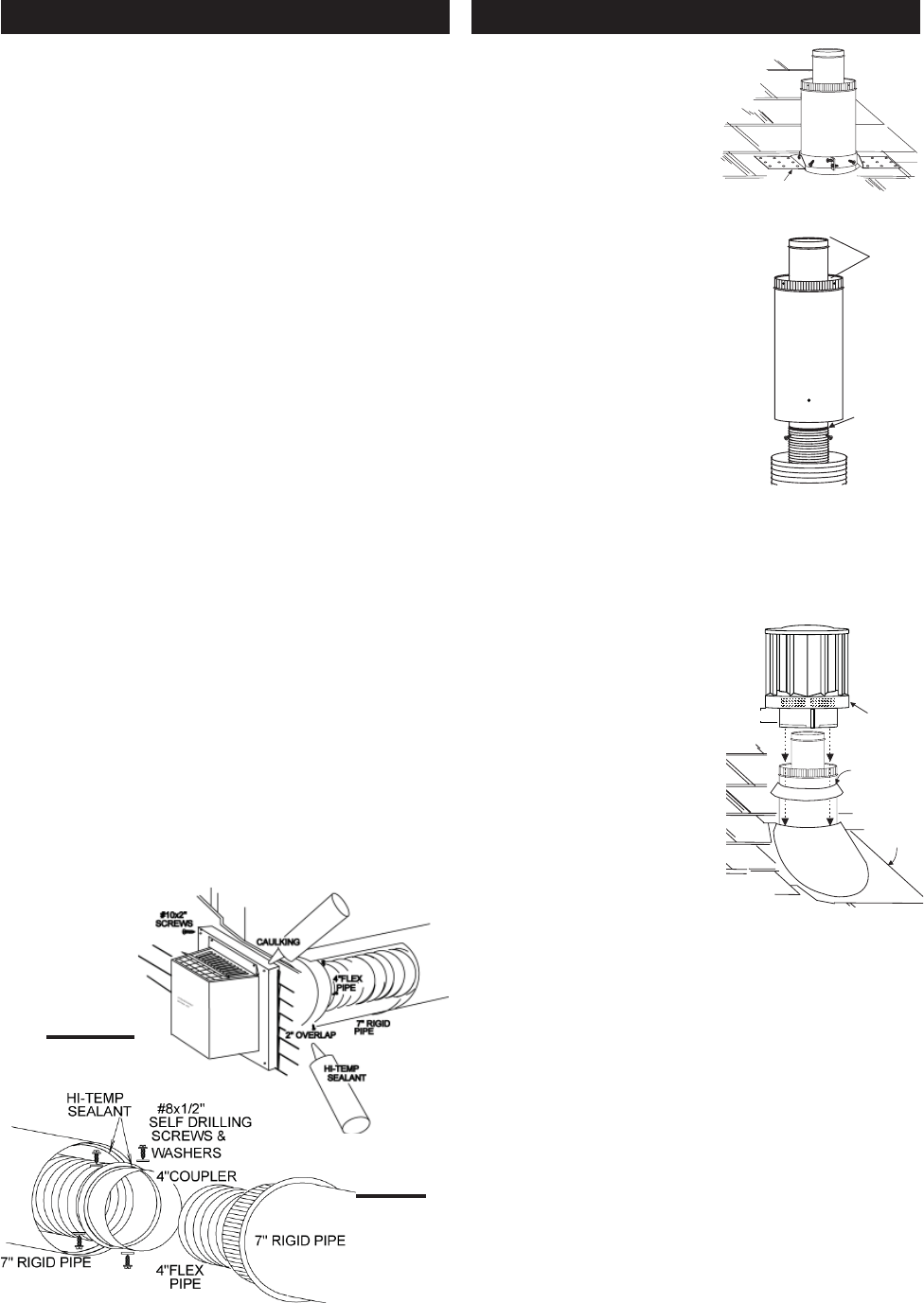
1. Stretch the 4" diameter aluminium fl exible liner to the re-
quired length taking into account the additional length needed
for the fi nished wall surface.
Spacers are attached to the 4" inner fl ex liner at predetermined
intervals to maintain a 1-1/4" air gap to the 7" outer stove pipe.
These spacers must not be removed.
Slip a 4" diameter length of aluminium fl exible liner a minimum
of 2" over the inner sleeve of the air terminal. Secure to the
sleeve using 3 screws. Seal the joint and screw heads using
the high temperature sealant.
2. Slip the fi rst section of 7" diameter stove pipe a minimum
of 2" over the outer sleeve of the air terminal. Secure to the
sleeve using 3 screws. Seal the joint and screw heads using
high temperature sealant.
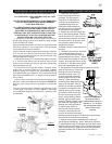
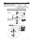
3. Insert the liners through the fi restop / vent pipe shield.
Holding the air terminal (lettering in an upright, readable
position), secure to the exterior wall. Make weather tight by
sealing with caulking (not supplied). The air terminal mounting
plate may be recessed (up to 1½" maximum) into the exterior
wall or siding.
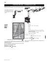
4. If more than one length of liner needs to be used to reach
the stove, couple them together as illustrated in FIGURE 21.
Seal the joints using the same procedure as described
above.
The vent system must be supported approximately every
10 feet along a horizontal run. Use supports or equivalent
non-combustible strapping to maintain the 1" clearance from
combustibles.
HORIZONTAL VENTING INSTALLATION
FIGURE 20
FIGURE 21
ROOF SUPPORT
DO NOT CLAMP
THE FLEXIBLE
ALUMINIUM
LINER.
AIR
TERMINAL
CONNECTOR
INNER FLEX
LINER
OUTER FLEX
LINER
INNER
SLEEVE
HIGH
TEMPERATURE
SEALANT
Spacers are attached to
the inner fl ex liner at
predetermined intervals to
maintain a 1-1/4” air gap to
the outer fl ex liner. These
spacers must not be
removed.
STORM COLLAR
FLASHING
CAULKING
WEATHER
SEALANT
2”
AIR INLET
BASE