


6
W415-0384 / D / 09.13.05
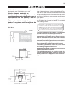
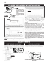
FIGURE 2
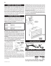
Move the insert close to its final position inside the wood-
burning fireplace. This unit is equipped with 4 levelling
screws located in the four inside corners beneath the log
support. Level using the levelling screws to eliminate rock-
ing or excessive noise when the fan is in operation. Once
the unit is level, move it partially into place within the fire-
place to allow for all connections to be made. It is not prac-
tical to level the insert once it has been installed. Deter-
mine the required depth prior to installing the unit and ad-
just the four levelling screws accordingly.
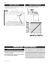
Chimney installation must conform to both national and
local code requirements. The chimney must be lined with
one 2" or 3" diameter liner for intake and one 3" diameter
liner for exhaust. The minimum and maximum vent
lengths are 10 and 35 feet respectively. Recommended
Napoleon kits come in 3 lengths:
While the liners must be continuous from the fireplace to
the chimney cap, to achieve the needed length, they may
be coupled, using an approved coupler.
We recommend that exhaust vents that pass through
unheated spaces, such as a garage or attic, be
wrapped in a protective sleeve to minimize condensa-
tion and reverse flow symptoms. See Trouble Shooting
for details.
This unit is approved for use with a 2" liner for air intake
and a 3" liner for exhaust. For best performance, how-
ever, it is recommended to use two 3" liners.
If a 2" liner is used for the intake, it may be necessary to
adjust the primary air shutter.
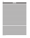
1. OUTSIDE: Slip the
one end of a liner a mini-
mum of 2" over the
sleeve of the air terminal.
Secure using 3 screws.
Then seal the joint and
screw heads with high
temperature sealant. Re-
peat with the other liner.
NOTE: We recommend that the other end of the exhaust
liner be marked to eliminate the exhaust liner being con-
nected to the intake collar at the unit.
2. Gently stretch the liners to the required lengths and in-
sert into the chimney. Trim and fit the flashing plate to suit
the chimney termination. Place the air terminal onto the top
of the chimney. Make weather tight by sealing with caulking
(not supplied). Fasten to the chimney with screws and plugs
(not supplied).
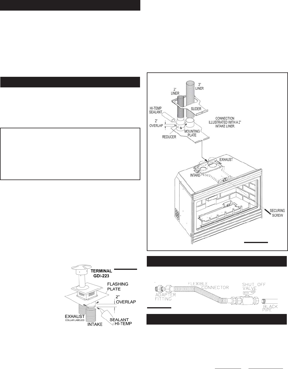
Install suitable supply piping connection to a flex connector
(as per local gas codes).
FIGURE 4
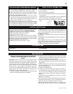
For ease of accessibility, an optional remote wall switch
or millivolt thermostat may be installed in a convenient
location. Route 2-strand solid core millivolt wire from
the gas fireplace insert to the wall switch / millivolt ther-
mostat. The recommended maximum lead length de-
pends on the wire size: WIRE SIZE MAX. LENGTH
14gauge 100 feet
16gauge 60 feet
18gauge 40 feet
Do not connect either the wall switch, thermo-
stat or gas valve to electricity (110 VOLTS).
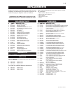
INSERT VENT CONNECTION
CHIMNEY CONNECTION
WALL SWITCH / THERMOSTAT
GAS INSTALLATION
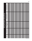
FIGURE 3
1-2" & 1-3" DOUBLE PLY ALUMINUM LINER-INLET AND EXHAUST &
2-3" TO 2" REDUCER:
GDI-2320KT VENT KIT 20FT
GDI-2325KT VENT KIT 25FT
GDI-2335KT VENT KIT 35FT
2-3" DOUBLE PLY ALUMINUM LINER-INLET AND EXHAUST:
GDI-320KT VENT KIT 20FT
GDI-325KT VENT KIT 25 FT
GDI-335KT VENT KIT 35 FT
3. INSIDE: Remove the securing screw from the front of the
vent mounting plate. Pull the vent mounting plate only, back
into the track, to the front stop. Start the slider back into
position. Re-secure the screw. The insert may now be
pushed into its final position inside the woodburning fire-
place, and the screw tightened until the slider has been
pulled tight to the front stop.
4. Route the flex liners through the slider. Attach and secure
the liners to the vent mounting plate using the same proce-
dure as before, ensuring that the marked exhaust liner is
attached to the exhaust collar.