


10
W415-0384 / D / 09.13.05
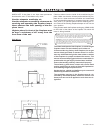
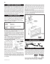
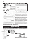
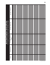
FIGURE 9
BLOWER ACCESS COVER
1. Turn off the electri-
cal power and the gas
supply to the fireplace
insert.
2. Open the glass door
and remove the logs
and fibre bricks, if in-
stalled.
3. Remove the blower access cover held on with 4 screws.
4. Remove the blower mounting plate with the blower
attached.
NOTE: Check the blower gasket for damage. Replace if
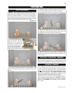
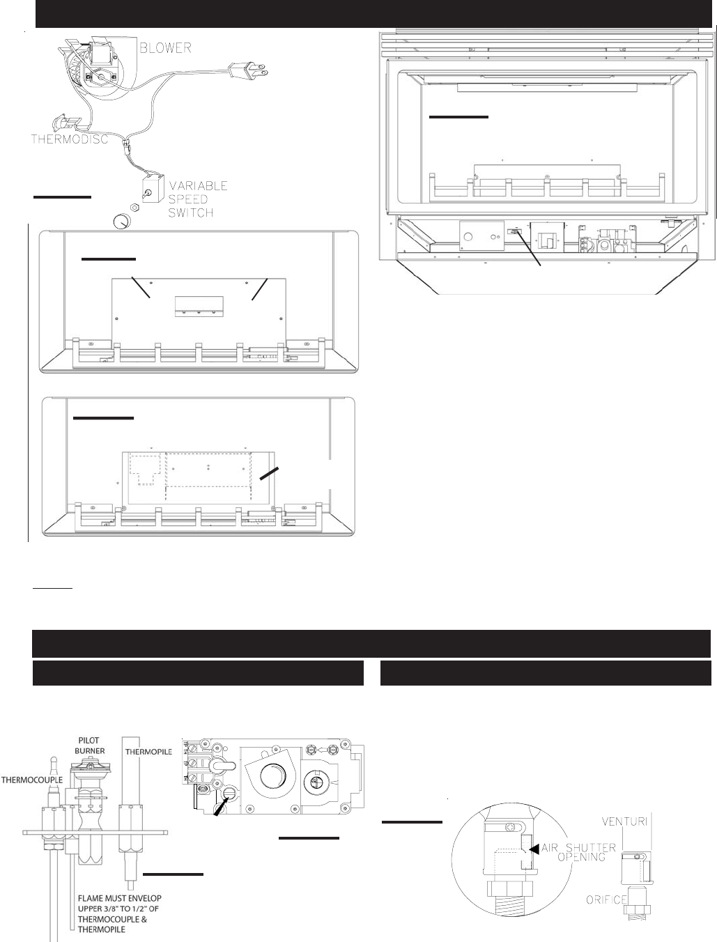
shutter will cause a more yellow flame, but can lead to
carboning. Opening the air shutter will cause a more blue
flame, but can cause flame lifting from the burner ports.
FIGURE 12
Air shutter adjustment must only be done by a qualified
gas installer!
FIGURE 14
The flame may not appear yellow immediately; allow 15 to
30 minutes for the final flame colour to be established.
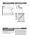
ADJUSTMENTS
PILOT BURNER ADJUSTMENT VENTURI ADJUSTMENT
FIGURE 13
P
I
P
I
PILOT SCREW
L
O
T
N
O
L
O
T
H
I
L
O
F
F
O
damaged.
5. Disconnect the two blower wires. Remove the blower
from the mounting plate and replace.
For thermodisc replacement: Remove the mounting
bracket secured to the underside of the burner base. Re-
move the thermodisc from the bracket and replace.
6. Reconnect the two wires. Re-install the blower gasket.
Reattach the blower mounting plate and blower access
cover. Replace the logs. Close the fire viewing door.
7. Turn the gas supply and electricity back on.
Because the blower is thermally activated, when turned on,
it will automatically start approximately 5-15 minutes after
lighting the fireplace insert and will run for approximately
30-45 minutes after the fireplace insert has been turned
off. Use of the fan increases the output of heat.
Drywall dust will penetrate into the blower bearings caus-
ing irreparable damage and must be prevented from com-
ing into contact with the blower or its compartment. Any
damage resulting from this condition is not covered by the
warranty policy.
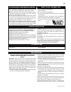
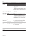
BLOWER REPLACEMENT INSTALLATION
FIGURE 11
THERMODISC / BRACKET ASSEMBLY
FIGURE 8
r
e
d
w
h
i
t
e
b
l
a
c
k
BLOWER ACCESS COVER REMOVED
MOUNTING
PLATE
FIGURE 10