


9
W415-0675 / A / 03.28.08
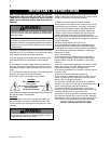
HARDWIRE INSTALLATION
HARD WIRING CONNECTION
If it is necessary to hard wire this
fi replace, a qualifi ed electrician
may remove the cord connection,
and wire the unit directly to the
house hold wiring.
This fi replace must be electrically
connected and grounded in ac-
cordance with local codes, if hard
wired. In the absence of local
codes, use the current CSA C22.1
CANADIAN ELECTRICAL CODE
in Canada or the ANSI/NFPA 70-
1996 NATIONAL ELECTRICAL
CODE in the United States.
CAUTION Ensure all power is
turned off before hard wiring this
fi replace.
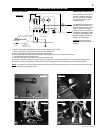
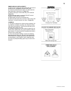
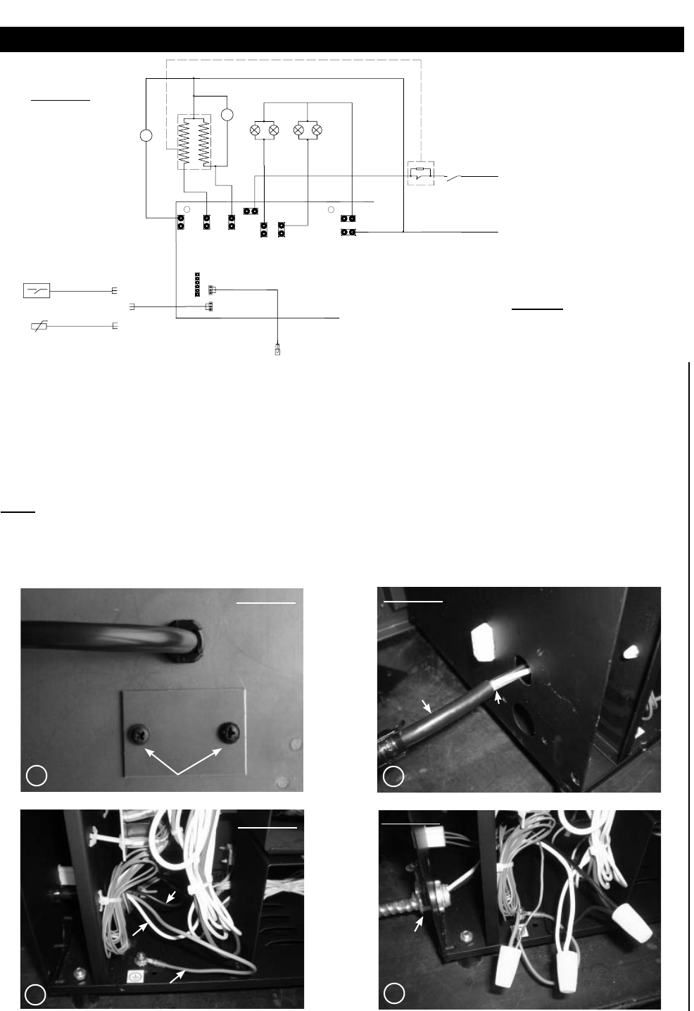
1. Remove cover plate located beside the power cord to reveal the 7/8” wire hole.
Discard cover plate, screws and insert a box connector into the hole.
2. Remove the lower back panel from the fi replace to expose wiring.
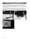
3. Remove the power cord strain-relief from the side of the fi replace and cut the cord where shown below.
This will be the hardwire connection point.
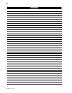
4. Feed the supply wires through the box connector and the grommet.
5. Using wire connectors connect the common (white) wires together, then the hot (black) wires, and then the ground (green) wires.
6. Ensure the newly connected wires are kept away from the rotating parts and the circuit board, and re-install the back panel.
NOTE: This fi replace must be serviced from the back, leave enough wire so that the fi replace can be removed from the enclosure with-
out disconnecting the power supply wires.
Remove 2 screws on cover plate.
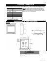
FIGURE 5
FIGURE 4
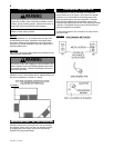
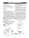
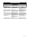
ELECTRIC DIAGRAM
2
3
5W
IF YOU PUT IN THE TEMPERATURE
SENSOR ON THE WALL.PLS CHOOSE 2
IF YOU USE THE
TEMPERATURE
SENSOR.PLS CHOOSE 1
2
1
TEMPERATURE
CONTROL SWITCH
t
10-10
5-5
4-4
10
-
10
1-1
9-9
6-6
2-2
3-3
1
2
-
12
8-8
PTC
t105!
R
EM
O.
SIP2
RECEIVER
MAIN C
ONTROL
P
OW
ER
2
3
5W
N
L
F
L
A
M
EM
O
TOR
~
M
BLO
W
E
R
M
O
TO
R
H
EA
T
ER 2
~
M
H
EAT
ER
1
TEMPERATURE
SENSOR
t
[
+
k
_
R
G
TEM.
P-N0
H2
H1+
FAN
P-L
P-
NI
MO
TOR
LAMP
FI
RE
7-7
2
3
4
1
Hot Wire
Cut
Power Cord
FIGURE 6
FIGURE 8
FIGURE 7
Final Connection
Common Wire
Ground Wire
Box
Connector