19
W415-0661 / C / 02.20.08
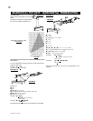
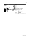
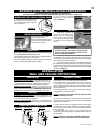
Do not over tighten. The gasket
needs only to be snug against the
fi rebox. FIGURE 45.
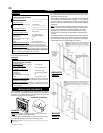
1. Remove the 7" diameter cap
from the top of the fi replace and re-
secure it over the 7" collar located
at the rear of the unit. Press fi rmly
on the cap while securing to ensure
an airtight seal. Do not damage the
gasket.
FAILURE TO INSTALL THE CAP WILL CAUSE THE FIRE-
PLACE TO FUNCTION IMPROPERLY AND CAN CAUSE
INJURY OR PROPERTY DAMAGE.
2. Remove the plate covering the 4" diameter fl ue opening (seen
inside the top of the 7" diameter collar) and discard. Try not to disturb
the retaining ring or the gasket beneath. Re-secure the ring and gasket
using the screws removed from the plate.
3. From inside the fi rebox, insert the 4" fl ue pipe assembly through
the heat shield and out through the retaining ring. Secure the assembly
to the rear and top of the unit using 4 #8 x ¾" Hex Head Wildrill screws
supplied. Do not over tighten. The gasket needs only to be snug against
the fi rebox. FIGURE 46.
BGD36CF(G) PRE-INSTALLATION PREPARATION
REAR EXIT:
TOP EXIT:
(THIS PROCEDURE IS NOT REQUIRED FOR THE BGD42CF)
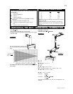
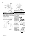
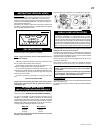
REMOVING THE VALVE ACCESS DOOR
1. The valve access door rotates on the
pins attached to the side frame. Lift the
valve access door off the pins to operate
the main glass door.
FIGURE 43
FIGURE 45
FIGURE 46
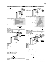
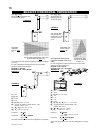
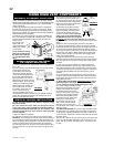
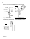
For optimum performance, it is recommended that all horizontal runs have a 1" rise per foot.
HORIZONTAL VENT SECTIONS: - A minimum clearance of 1" at
the bottom and sides of the vent and 2" at the top on all horizontal
runs to combustibles is required. The fi restop spacer (W010-1774)
supplied with the unit must be used to maintain this clearance.
VERTICAL VENT SECTIONS: - A minimum of 1" all around the vent
pipe on all vertical runs to combustibles is required except for clear-
ances in fi replace enclosures. See "MINIMUM ENCLOSURE CLEAR-
ANCES" section. Use fi restop spacer W500-0096 (not supplied).
HORIZONTAL VENT SECTIONS: A minimum clearance of 2" all
around the vent pipe on all horizontal runs to combustibles is required.
Use fi restop spacer W010-1778 (supplied).
VERTICAL VENT SECTIONS: A minimum of 1" all around the vent
pipe on all vertical runs to combustibles is required. Use fi restop spacer
W500-0028 (not supplied).
INSTALLATION
WALL AND CEILING PROTECTION
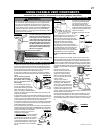
HORIZONTAL INSTALLATION
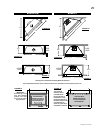
RECTANGULAR
HOLE
11 3/8”
9 7/8”
BGD36CF(G)
RECTANGULAR
HOLE
16 1/4”
BGD42CF
14 7/16”
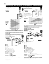
FIGURE 47
BGD36CF(G) ONLY
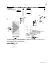
This application occurs when venting through an exterior wall.
Having determined the correct height for the air terminal location,
cut and frame a hole in the exterior wall 9 7/8" wide by 11 3/8" high
to accommodate the fi restop assembly. Dry fi t the fi restop assembly
before proceeding to ensure the brackets on the rear surface fi t within
the horizontal framing.
As an alternative to framing, the vent pipe can be enclosed in the wall
using Napoleon® vent sleeve VS47KT.
NOTE: THE FIRESTOP ASSEMBLY MUST BE INSTALLED WITH
THE VENT SHIELD TO THE TOP.
The length of the vent shield may be cut shorter for combustible walls
that are less than 8 1/2" thick but the vent shield must extend the full
depth of the combustible wall.
1. Apply a bead of caulking (not supplied) around the outer edge of
the inside surface of the fi restop assembly, fi t the fi restop assembly
to the hole and secure using the 4 screws (W415-0026) supplied in
your manual baggy.
2. Once the vent pipe is installed in its fi nal position, apply high
temperature sealant W573-0002 (not supplied) between the pipe,
and the fi restop.
NOTE: DO NOT FILL THE CAVITY BETWEEN THE VENT PIPE
AND THE FIRESTOP SLEEVE WITH ANY TYPE OF MATERIAL.
BGD36CF(G)
BGD42CF
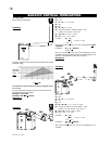
DOOR OPERATION
To access the lower door latch,
open the Valve Access
Door as illustrated. Release the top
and bottom door latches, located at
the right side of the door.
FIGURE 44
FIGURE 44
Before attaching elbows to the collars on the back of the fi replace,
1½" will need to be trimmed off the 4" collar.
From inside the fi rebox, insert the 4" fl ue pipe / gasket assembly
(provided) through the rear of the fi rebox.
Secure the gasket assembly to the rear and top of the unit using
4 #8 x 3/4" Hex Head Wildrill screws supplied.
!
WARNING


