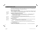
The XP600 is constantly monitoring its own components, as well as all critical services, such as AC Power
and the Telephone line, to insure that it is always ready to provide the protection for which it was designed.
When a system trouble does occur, it will caution you by lighting the yellow üüSYSTEM light and beeping
the keypad buzzer. If you cannot immediately clear the system trouble, the system can still be used.
Simply press D to view the trouble as described below, and then arm the system.
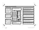
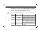
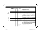
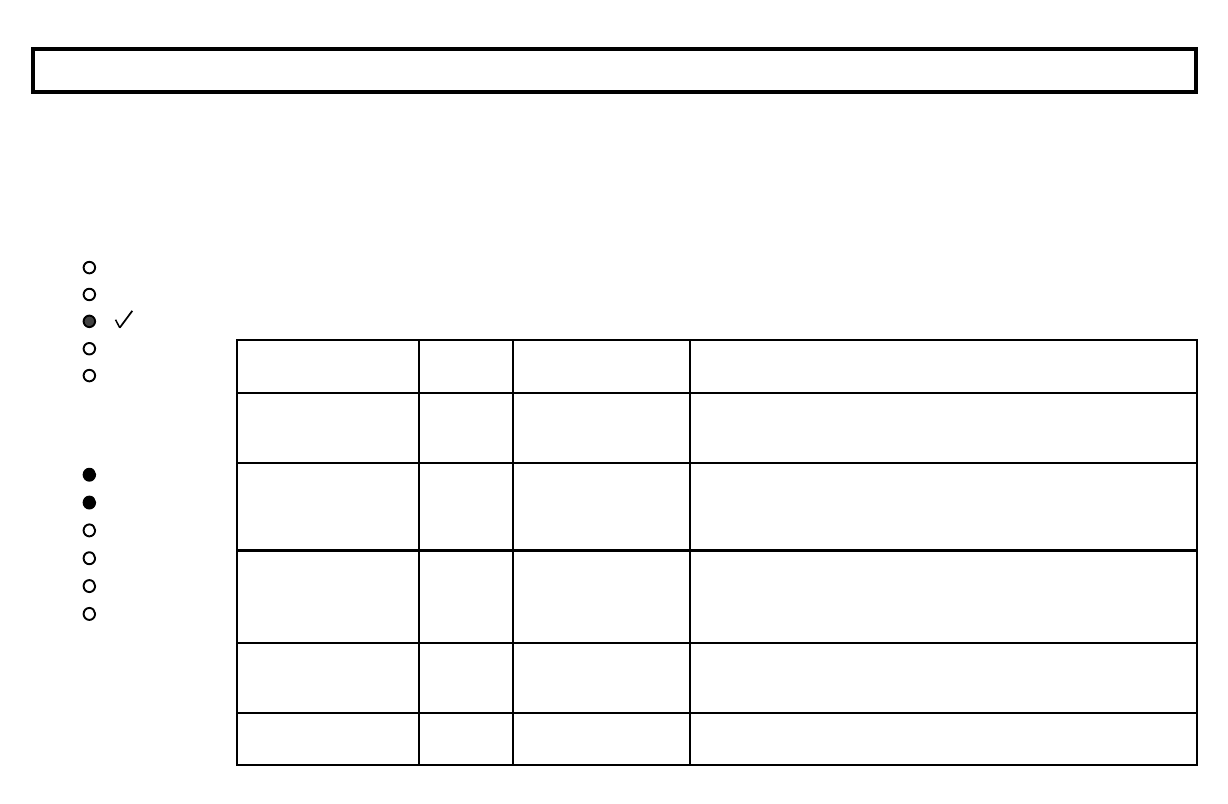
In order to determine the nature of the trouble, press D, count the number of keypad beeps and observe
the number of the illuminated zone light. Refer to the following table to determine the cause of the trouble.
If there is more than one trouble to be viewed, pressing D will scroll to the next, and then exit the
üüSYSTEM mode if there are no additional troubles to view.
ü ü System Troubles
Keypad Beeps or
üüSYSTEM Flashes
Zone light
ON
System Trouble
Condition
Action
1 Beep
1 AC Power Failure This trouble will occur if AC power is not present. Make sure
system transformer is plugged into AC receptacle and check
circuit breaker, otherwise call installing company for service.
1 Beep
2 Low Battery If there has been a recent power failure, the battery may be
partially depleted and must be recharged by the control
panel. If the trouble does not go away in 24 hours, call in-
stalling company for service.
1 Beep
3 Communication
Failure
The system was not able to report to central station. If this is
due to a temporary interruption in the telephone service, the
trouble can be cleared when the service is restored by press-
ing D. Otherwise, call installing company for service.
1 Beep
4 Telephone Line Cut The telephone line has failed. If telephone service has been
temporarily interrupted, the trouble will clear it is when re-
stored. Otherwise, call installing company for service.
2 Beeps
1 Bell/Siren Trouble There is a problem with the Bell or Siren. Call installing com-
pany for service.
FIRE
AC
SYSTEM
READY
ZONE 3
ZONE 1
ZONE 2
ZONE 5
ZONE 6
ZONE 4
ARMED
12
Oi218a.pub
page 12
Thursday, December 18, 1997 18:29


