


PAGE 16 — ST4125G/ST6125G SUBMERSIBLE PUMP • OPERATION MANUAL — REV. #0 (11/18/10)
CONTROL BOX INSTALLATION
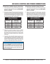
Connecting SW-1WOPA Float Switches to Control
Box
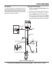
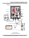
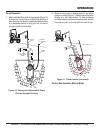
1. Remove the fl oat switch input connector housing, then
route the fl oat switch wires through the cable gland on
the control box. Attach the wires of the fl oat switch to
the terminal block as indicated by Table 5 and Figure 9.
2. Tighten the connector housing to ensure a tight fi t
between the cord and the connector body. This will
prevent the cable from pulling out of the terminal block
and also prevent moisture from entering the control box.
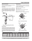
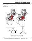
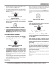
3. Determine the tether length of the fl oat switch wires
then secure fl oat switch wires to pump discharge hose.
See Figure 3 and Table 2 to determine the pumping
range.
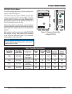
Table 5. Dual Float switch Connections
Float
Switch
Terminal
Block No.
Wire
Color
Start
TB1-A1
TB1-A2
Black
White
Stop
TB1-A3
TB1-A4
Black
White