


ST4125G/ST6125G SUBMERSIBLE PUMP• OPERATION MANUAL — REV. #0 (11/18/10) — PAGE 11
ST4125G/ST6125G — COMPONENTS
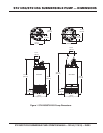
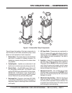
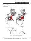
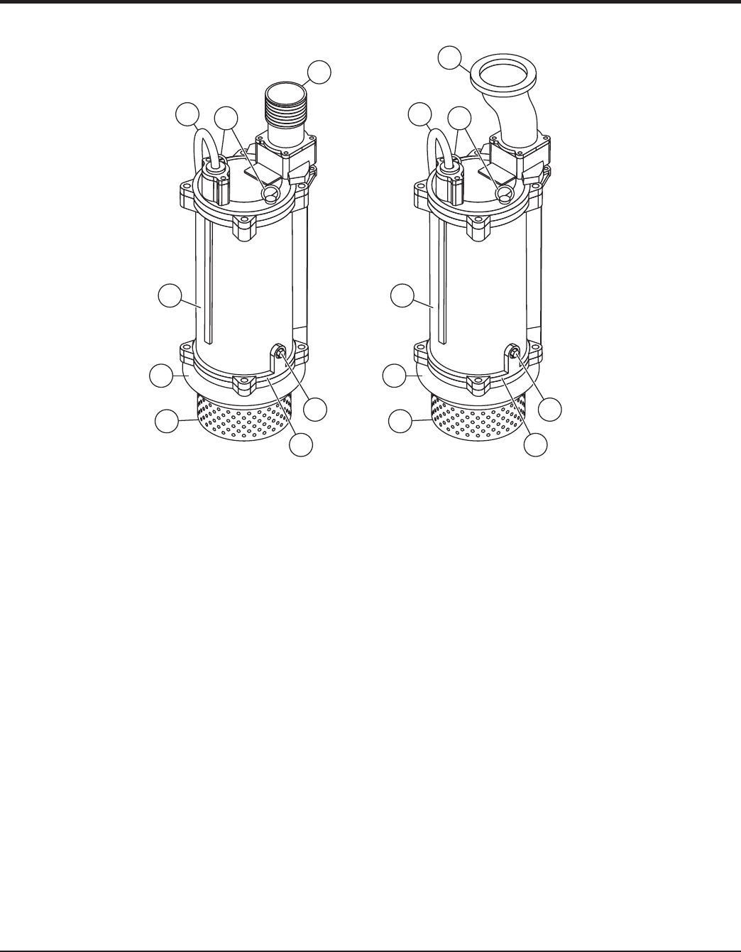
Figure 2 shows the location of the basic components, for
the ST4125G and ST6125G submersible pumps. Listed
below is a brief explanation of each component.
1. Strainer Base – This strainer base is made of stainless
steel which is resistant to hardware corrosion. For
dewatering purposes, always place the strainer base
on a platform.
2. Volute/Impeller – Impellers are constructed of cast
ductile iron to minimize wear and prolong service life.
3. Electric Motor – The ST4125G pump utilizes a 60
Hz, three-phase, 230/460 VAC, 10 HP electric motor
and the ST6125G pump utilizes a 60 Hz, three-phase,
230/460 VAC, 15 HP electric motor. Consult with a
licensed electrician before connecting motor to a power
source. Observe all city and local safety codes.
4. Discharge Port – Connect a 4-inch hose (ST4125G)
or 6-inch hose (ST6125G) to this port. Remember to
adequately support the discharge hose to avoid stress
on the pump.
5. AC Power Cable – These pumps are supplied with a
50 ft. (15.2 meters) AC power cable. Always check the
cable for signs of wear. NEVER use a defective power
cable. Replace the cable immediately if the cable is
worn or defective.
6. Eye Bolts – Always lift the submersible pump by the
eye bolts using a chain and lifting device capable of
lifting about 400 lbs. NEVER lift the pump by its power
cord! Lifting the pump by the power cord will cause
undue stress on the cord and ultimately the cord will
become dislodged from the pump.
7. Mechanical Seal Oil – This oil-fi lled seal provides
lubrication when running the pump dry. NEVER run the
pump dry! Running the pump dry will cause severe
damage to the pump.
8. Mechanical Seal Oil Plug – Remove this plug to
check and add ISO VG32 lubrication oil, Mobile DTE
24, turbine oil 90 or equivalent to the oil chamber. This
oil protects the mechanical seal. Oil chamber should
be full enough to cover seal spring.
1 1
4
4
55
88
77
66
3 3
2 2
Figure 2. Submersible Pump Components