


PAGE 22 — ST-3050D — PARTS & OPERATION MANUAL — REV. #1 (11/18/02)
ST-3050D SUB. PUMP/CTRL. BOX — INSTALLATION (MCP102/104)
DANGER:
Remember this control box contains hazardous voltages.
Disconnect all sources of power before installing or servicing.
There exists the possibility of electrocution, electric shock or
burn, which can cause severe bodily harm or even
death
!
Remember the
MCP102 Control Box
is to be used only for
230 VAC 3-phase applications and the
MCP 104 Control Box
is for 460 VAC 3-phase applications. Neither control box has
float switch capability.
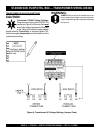
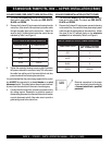
POWER CORD REQUIREMENTS
When routing the three phase power via a power cord to the
control box,
ALWAYS
use the correct wire size. Please reference
Table 3 (Cord Length/Wire Size) to determine the correct wire
size. Incorrect wire size can adversely affect the performance of
the pump.
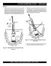
CONTROL BOX MOUNTING
Mount the control box in an
upright vertical position
. Make sure
the control box is securely fastened to a flat surface, that is free
of dust, dirt, moisture or any elements that may contaminate or
erode the electronic components of the control box.
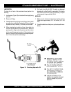
3-PHASE POWER CORD (INPUT TO BOX) INSTALLATION
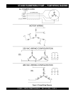
1. The three phase
input
power cord should have four wires.
Each wire is color coded. The colors are RED, WHITE,
BLACK and GREEN.
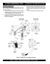
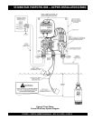
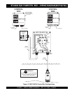
2. Remove the 3-phase AC input connector housing from the
control box, then route the three phase input power cable
through the cable gland on the control box. Attach the
wires to the terminal block on the electronic overload unit
inside the control box as indicated by Table 5 and Figure 15.
3. Tighten the connector housing to ensure a tight fit between
the power cord and the connector body. This will prevent
the cable from pulling out of the terminal block and also
prevent moisture from entering the control box.
It is recommended that the power being supplied to the control
box
ALWAYS
be connected to a
circuit breaker
or a
quick
disconnect
switch. This safety feature allows for quick removal
of power from the control box in the event of an emergen
cy.
4. Connect the other end of the 3-phase input power cord to
the voltage source. Remember to provide a means of
disconnecting the power from the control box (circuit breaker
or quick disconnect switch). Also make sure to provide a
good earth ground to the control box.
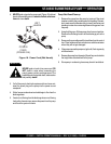
ELECTRONIC OVERLOAD SETTING (230 VAC, 3Ø)
1. Using a small flat-blade screwdriver, set the
amperage dial pointer on the electronic
overload unit to 14.2 amps.
ELECTRONIC OVERLOAD SETTING (460 VAC, 3Ø)
1. Using a small flat-blade screwdriver,set the
amperage dial pointer on the electronic
overload unit to 7.1 amps.
3-PHASE POWER INSTALLATION (OUTPUT TO PUMP)
1. The three phase
output
power cord should have four wires.
Each wire is color coded. The colors are RED, WHITE,
BLACK and GREEN.
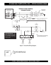
2. Remove the 3-phase AC output power connector housing
on the control box, then route the three phase output power
cable through the cable gland on the control box. Attach
the wires to the AC terminal blocks on the
electronic
overload
unit as indicated by Table 6 and Figure 15.
14.2
5.1
6.3
7.1
5.1
6.3