


DRY PRIME PUMP — OPERATION AND PARTS MANUAL — REV. #3 (10/06/08) — PAGE 21
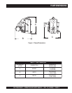
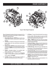
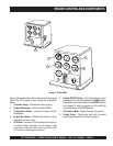
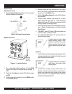
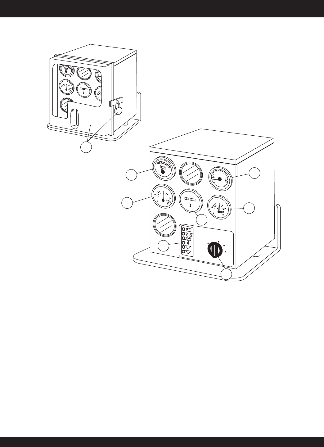
Figure 5 shows the location of the components for the engine
control box. The function of each component is described
below:
1. Voltmeter Gauge – Indicates the battery charge.
2. Engine Tachometer – Monitors engine RPM's.
3. Temperature Meter - Indicates engine coolant
temperature.
4. Engine Hour Meter – Displays the number of hours
the engine has been in use.
5. LED Panel– contains LED fault indicators that light up
to indicate battery discharge, low oil pressure, high
temperature, alternator failure and V-belt failure. LED
will remain lit indicating fault until reset.
ENGINE CONTROL BOX COMPONENTS
6. Engine ON/OFF Switch – Turn the knob here to start
the engine. Turn the knob clockwise to the RUN position,
then continue turning clockwise to the START position
and release. To stop the engine turn the knob fully
counterclockwise to the OFF position.
7. Oil Pressure Meter - Monitors engine oil pressure.
8. Vandal Cover - Close cover and lock to prevent
unauthorized personnel from starting engine.
Figure 5. Control Box
VDO
x100
RPM
2
0
3
0
4
0
10
0
8
1
0
1
2
1
4
1
6
VDO
6
0
8
0
0
2
0
0
1
P
S
I
4
0
2
bar
3
4
5
V
D
O
2
6
0
3
0
0
1
2
0
2
0
0
5
0
9
0
1
2
0
1
5
0
C
F
VDO
0
0
025
5
QUARTZ
H
O
U
R
S
O
F
F
R
U
N
START
AUTO START
(WHEN EQUIPPE
D)
I
II
I
I
I
0
P
AUX
1
AUX
2
8
V
D
O
x
1
0
0
R
P
M
20
30
40
10
0
8
10
12
14
16
V
D
O
60
80
0
20
0
1
PSI
40
2
b
ar
3
4
5
V
D
O
2
6
0
3
0
0
1
2
0
2
0
0
5
0
9
0
1
2
0
1
5
0
C
F
VDO
00
025
5
QUARTZ
HOURS
O
F
F
RUN
START
A
U
T
O
S
T
A
R
T
(
W
H
E
N
E
Q
U
I
P
P
E
D
)
I
III
0
P
AUX
1
AUX
2
1
7
3
5
2
4
6