


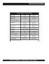
DRY PRIME PUMP — OPERATION AND PARTS MANUAL — REV. #3 (10/06/08) — PAGE 19
PUMP COMPONENTS
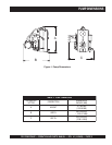
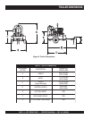
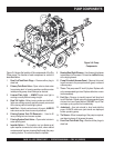
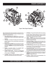
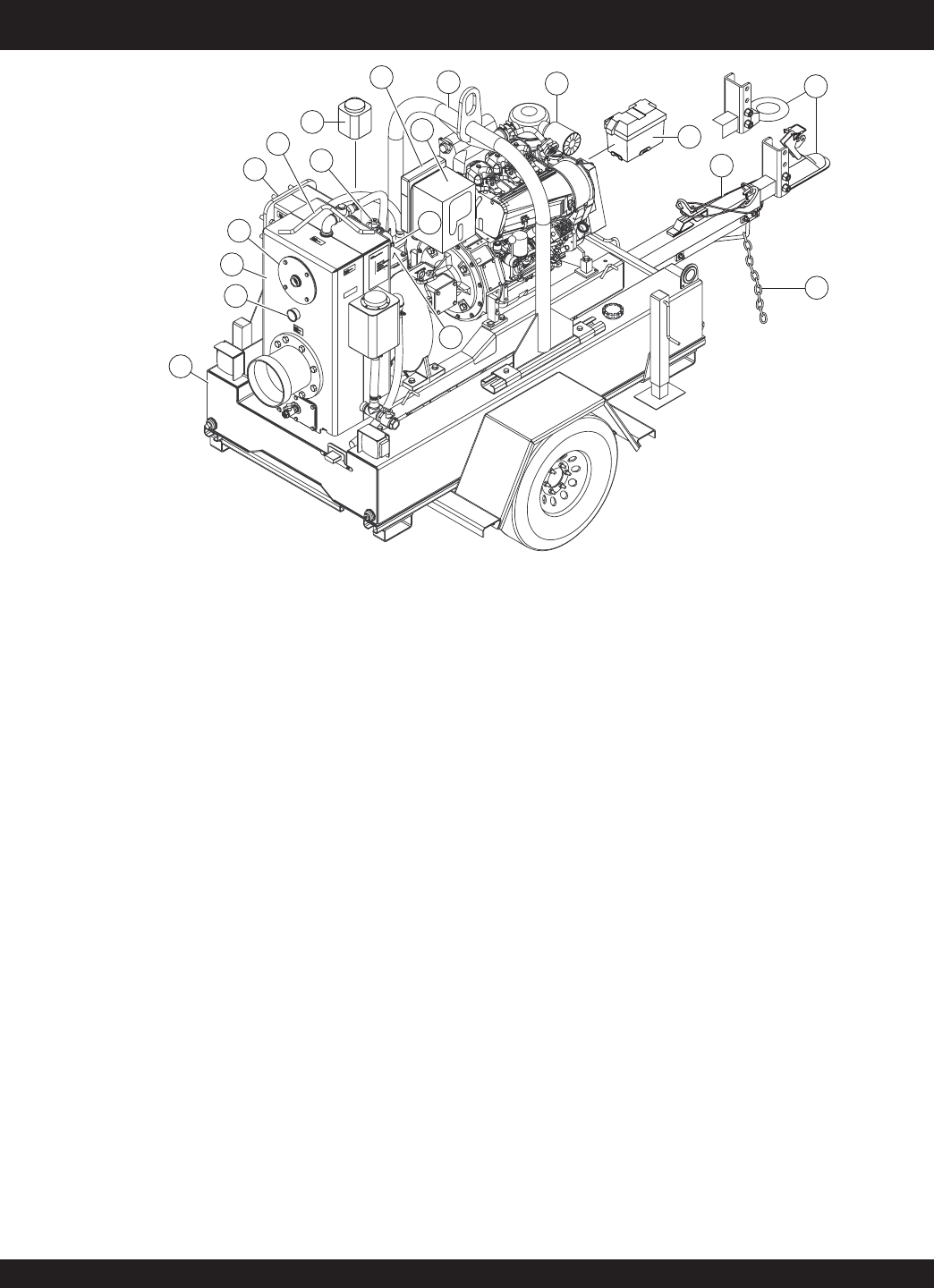
Figure 3-B. Pump
Components
Figure 3-B shows the location of the more components of
the Dry Prime pump, The function of each component or
control is described below:
16. Safety Chain – ALWAYS attach safety chain to the
towing vehicle. NEVER tow the pump with the safety
chain unattached! See towing section of this manual.
17. Towing Coupler/Ring – Attach this coupler to the towing
vehicle. Use only the specified ball diameter as indicated
on your coupler (2-5/16). Use of any other ball diameter
will create an extremely dangerous condition which can
result in separation of the coupler and ball or ball failure. A
3-inch tow ring is also available as an option.
18. Ajustable Tow Tongue – Tow tongue is adjustable by
removing locking pin to adjust tongue length then
reinserting pin to lock tongue in place.
19. Battery – Unit uses a +12VDC wet battery Group 31.
20. Engine – These pumps are equipped with either a
Deutz F3L914 or F4L914 three or four cylinder air-
cooled diesel engine.
21. Skid Lifting Bail –When lifting of the pump skid is required,
attach a strap or chain of adequate lifting capacity to lift the
skid.
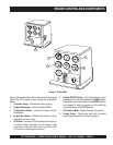
22. Engine Control Box – Vandal proof (lockable) engine
control box displaying engine guages, tachometer,
tempertature, battery voltage, hour meter, oil pressure
and ignition switch.
23. Document Box – Contains all documentation relating
to the pump or engine.
24. Vacuum Pump Mechanical Seal Oil Reservoir – Oil
level should always be maintained to the FULL level
marked on the bottle.
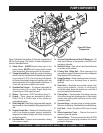
25. Backflush Valve – Open valve to backflush wellpoints
or to clean suction strainer.
26. Priming Tank Lifting Bail – When removing of the
priming tank is required, attach a strap or chain of adequate
lifting capacity to lift vacuum pump.
27. Pump Discharge – Attach discharge hose to this port.
ALWAYS make sure discharge hose is securely
attached.
28. Float Valve – Regulates and controls vacuum level
during pump operation. Consist of self-aligning
reinforced rubber hinge that doubles as a seal and a
one piece welded float assembly.
29. Priming Tank – Vacuum system that creates a vacuum
in the outer priming tank, drawing water in. Water drawn
into the outer priming tank then flows into the volute,
priming the pump.
30. Vacuum Gauge – Vacuum gauge for priming system.
Monitors air discharge. Required when troubleshooting.
31. Fuel Tank – Holds 140 gallons (530 liters) of diesel
fuel
32. Volute Inspection Cover – Remove this cover to
inspect or clear the impeller.
33. Vacuum Pump – This unit uses a direct-drive 60 CFM
vacuum pump to remove large volumes of air to obtain
priming for the pump.
16
17
18
19
20
21
24
23
22
25
26
27
28
29
30
31
32
33