


10
SECTION 7: LUBRICATION
Wheels- Rear wheels are provided with light oil
bearings. Place a few drops of SAE 30 oil on each
bearing once a season.
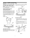
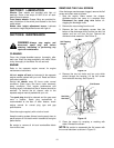
Front caster wheels- Grease fitting are provided for
easy lubrication of the swivel pins located on the front
caster wheel.
Nozzle door height adjustment levers- Lubricate
nozzle door height adjustment levers with light oil.
SECTION 8: MAINTENANCE
WARNING: Always stop engine and
disconnect spark plug wire before
cleaning, lubricating or performing any
repairs or maintenance.
CLEANING
Clean the chipper-shredder-vacuum thoroughly after
each use. Wash the bag periodically with water. Allow
to dry thoroughly in the shade. Do not use heat.
ENGINE
Refer to the separate engine manual for engine
maintenance instructions.
Maintain engine oil level as instructed in the separate
engine manual packed with your unit. Read and follow
instructions carefully.
Service air cleaner every 25 hours under normal
conditions. Clean every few hours under extremely
dusty conditions. Poor engine performance and
flooding usually indicates that the air cleaner should be
serviced. To service the air cleaner, refer to the
separate engine manual packed with your unit.
The spark plug should be cleaned and the gap reset
once a season. Spark plug replacement is
recommended at the start of each season; check
engine manual for correct plug type and gap
specifications.
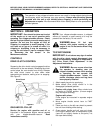
Clean the engine regularly with a cloth or brush.
Keep the cooling system (blower housing area) clean to
permit proper air circulation which is essential to engine
performance.
Be certain to remove all dirt and combustible debris
from muffler area.
REMOVING THE FLAIL SCREEN
If the discharge area becomes clogged, remove the flail
screen and clean area as follows.
1. Stop the engine. Make certain the chipper-
shredder-vacuum has come to a complete stop.
Disconnect the spark plug wire before un-
clogging the discharge chute.
2. Remove the vacuum bag from the unit.
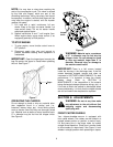
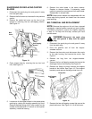
3. Remove the four self-tapping screws from the
bottom of the discharge chute, and the hex bolt, flat
washer and hex nut from the top. Remove the
discharge chute assembly. See Figure 12.
Figure 12
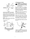
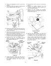
4. Remove the two hex bolts and hex nuts which
extend through the housing. Lift the flail screen
from inside the housing. See Figure 13.
Figure 13
5. Clean the screen by scraping or washing with
water. Reinstall the screen.
NOTE: Be certain to reassemble the flail screen with
the curved side down as shown in Figure 13
.
Hex Nut
Self-Tapping
Screws
Flail Screen
Hex Bolts
Hex Nuts